
Circuit breaker contact arc extinguishing device and circuit breaker thereof

A technology of arc extinguishing device and circuit breaker, which is applied to high-voltage air circuit breakers, circuits, high-voltage/high-current switches, etc. It can solve the problems of different transfer arc effects, achieve good arc extinguishing effect, simple overall structure, and improve electrical life Effect

Pending Publication Date: 2019-03-15
CHANGSHU SWITCHGEAR MFG CO LTD (FORMER CHANGSHU SWITCHGEAR PLANT)
View PDF0 Cites 2 Cited by
  • Summary
  • Abstract
  • Description
  • Claims
  • Application Information

AI Technical Summary

Problems solved by technology

However, due to the different materials and structural forms of the arc striker, the effect of transferring the arc is also different, so how to design a reasonable arc strike structure is a current research hotspot

Method used


Image

  • Circuit breaker contact arc extinguishing device and circuit breaker thereof
  • Circuit breaker contact arc extinguishing device and circuit breaker thereof
  • Circuit breaker contact arc extinguishing device and circuit breaker thereof

Examples


Embodiment 1

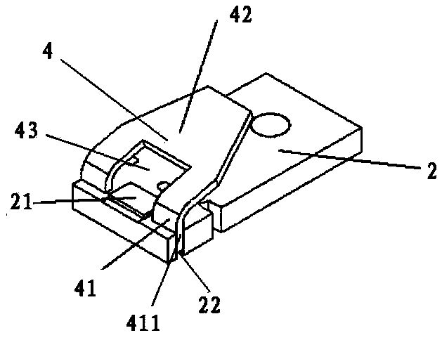
[0026] Such as figure 2 As shown, the arc runner 4 and the static guide rod 2 described in this embodiment are fixedly installed by riveting. Specifically, the static guide rod 2 is provided with grooves 22 on both sides of the static contact point 21 in a direction parallel to the rotation centerline of the movable guide rod, and the supporting leg 41 has a support portion 411 perpendicular to the static guide rod 2. The support part 411 is inserted into the groove 22 of the static guide rod 2, and the fixed installation of the arc runner 4 and the static guide rod 2 is realized by riveting connection.

Embodiment 2

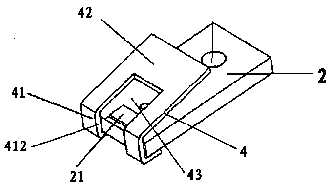
[0028] Such as image 3As shown, the arc striker 4 and the static guide rod 2 described in this embodiment are fixedly installed by welding. Specifically, the support leg 41 has a welded part 412 perpendicular to the static guide rod 2, and the welded part 412 cooperates with the end of the static guide rod 2 to realize the connection between the arc runner 4 and the static guide rod 2 through welding. Fixed installation.

[0029] see Figure 4-Figure 5 , describe the specific arc extinguishing principle of the contact arc extinguishing device of the circuit breaker of the present invention:

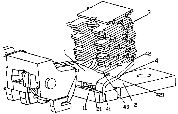
[0030] When a short-circuit large current passes through the circuit, the movable contact 11 and the static contact 21 repel each other due to the effect of electrodynamic repulsion, and an arc is formed between the movable contact 11 and the static contact 21. The side is electrically connected with the supporting leg 41 of the arc striker 4, Figure 4 It is the state when the movin...


PUM


Abstract

A circuit breaker contact arc extinguishing device and a circuit breaker thereof are disclosed. The contact arc extinguishing device comprises a moving guide rod, a static guide rod, an arc extinguishing grid plate group and arc striking plate fixedly mounted on the static guide rod. A movable contact and a static contact are fixed on the movable guide rod and the static guide rod respectively. The arc striking plate comprises two supporting legs with one end extending in the direction of the static contact, wherein the two supporting legs are arranged on two sides of the static contact and are electrically connected with the static guide rod, and a space for allowing the moving contact to pass through is formed between the two supporting legs. The arc striking plate also comprises an arcrunning track with the other end being away from the static contact and extending toward the arc extinguishing grid plate group. During the separation of the movable contact and the static contact from the beginning to the separation of the movable contact from the space, a distance from a connecting portion of the two support legs and the arc running track to the movable guide rod changes from adistance greater than a distance between the movable contact and the static contact to a distance smaller than the distance between the movable contact and the static contact. Therefore, electric arccan be quickly transferred to the arc striking plate, the ablation of the electric arc on the static contact is avoided, the electric service life of the circuit breaker is prolonged, the structure issimple, and the arc extinguishing effect is good.

Description

technical field [0001] The invention belongs to the technical field of low-voltage electrical appliances, in particular to a circuit breaker contact arc extinguishing device, and also relates to a circuit breaker using the contact arc extinguishing device. Background technique [0002] As an important component of the low-voltage power grid, the low-voltage circuit breaker can quickly break the circuit, especially when there is a short circuit and a large current in the circuit, so as to ensure that the power grid is not damaged. When the low-voltage circuit breaker breaks the current, an arc will be generated, and the arc will enter the arc extinguishing chamber to be divided and extinguished. If the arc burns on the moving and static contacts for a long time without being introduced into the arc extinguishing chamber, it will cause the failure of breaking current; even if the arc can be introduced into the arc extinguishing chamber, if it cannot leave the moving and static...

Claims


Application Information

Patent Timeline
IPC IPC(8): H01H33/10
CPCH01H33/10
Inventor 刘洪武马俊贤王铖
Owner CHANGSHU SWITCHGEAR MFG CO LTD (FORMER CHANGSHU SWITCHGEAR PLANT)
Learn More