Method for producing aviation gas turbine engine combustion chamber burner inner liner

An aviation gas turbine and production method technology, applied in the field of aviation technology equipment, can solve the problems of uneven gap between wall panels and heat shield ribs, poor cooling effect of flame tube, low welding quality, etc., and achieve dimensional tolerance and shape position The tolerance is easy to control, preventing the slot from being reduced or even blocked, and improving the working reliability.

Active Publication Date: 2014-01-01
BEIJING POWER MACHINERY INST
View PDF5 Cites 15 Cited by
  • Summary
  • Abstract
  • Description
  • Claims
  • Application Information

AI Technical Summary

Problems solved by technology
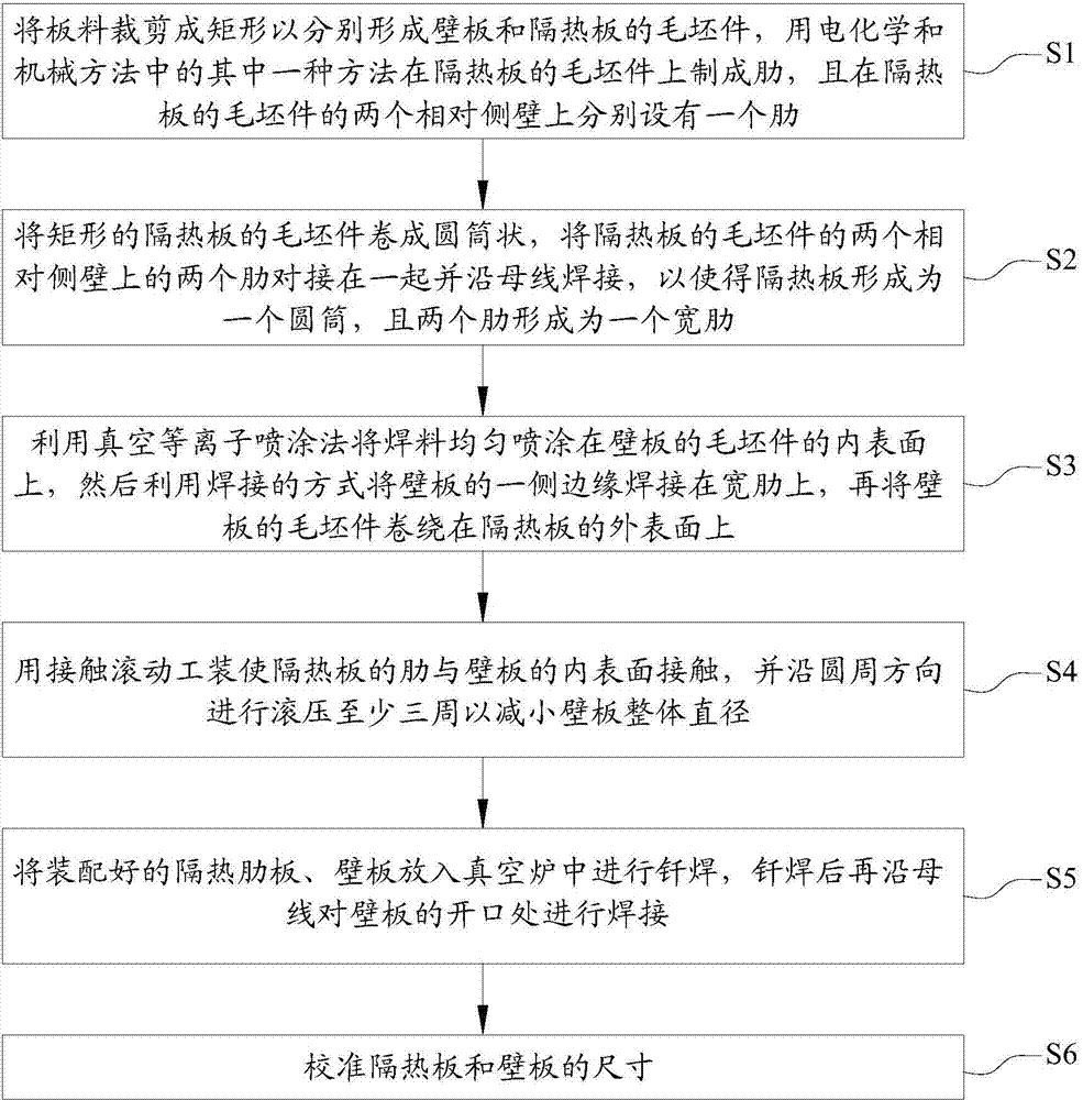
[0004] The key welding process of this method is located after the cylinder is formed, and the dimensional and shape tolerances of the cylinder are not easy to control. The gap between the wall plate and the rib of the heat insulation plate is likely to be uneven, and the amount of solder is Certainly, if the gap is too large, the welding quality may be low or even not welded, and if the gap is too small, the solder may melt and overflow, blocking the intercostal space
These defects can lead to poor cooling of the flame tube and even severe ablation

Method used


Image

  • Method for producing aviation gas turbine engine combustion chamber burner inner liner
  • Method for producing aviation gas turbine engine combustion chamber burner inner liner

Examples


Embodiment Construction

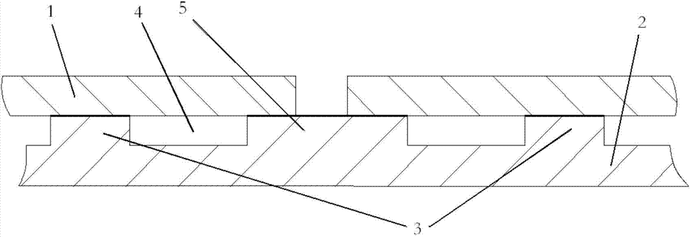
[0019] Embodiments of the present invention are described in detail below, examples of which are shown in the drawings, wherein the same or similar reference numerals designate the same or similar elements or elements having the same or similar functions throughout. The embodiments described below by referring to the figures are exemplary and are intended to explain the present invention and should not be construed as limiting the present invention.

[0020] In the description of the present invention, it should be understood that the orientation or positional relationship indicated by the terms "length", "width", "thickness", "upper", "lower", "inner" and "outer" are based on the attached The orientation or positional relationship shown in the figure is only for the convenience of describing the present invention and simplifying the description, and does not indicate or imply that the referred device or element must have a specific orientation, be constructed and operated in a...


PUM

PropertyMeasurementUnit
thicknessaaaaaaaaaa

Abstract

The invention discloses a method for producing an aviation gas turbine engine combustion chamber burner inner liner. The method comprises the following steps: S1, forming a blank part of a wall board and a blank part of a heat insulation board, and manufacturing ribs on the blank part of the heat insulation board; S2, rolling the blank part of the heat insulation board to be in a cylinder shape, enabling the two ribs on the two opposite side walls of the blank part of the heat insulation board to be in butt joint and be welded to from a wide rib; S3, spraying a welding flux on the inner surface of the wall board, welding one side edge of the wall board on the wide rib, and winding the blank part of the wall board on the outer surface of the heat insulation board in a rolling mode; S4, using a contact rolling tool for enabling the ribs of the heat insulation board to be in contact with the inner surface of the wall board; S5, placing the assembled heat insulation board and the wall board into a vacuum furnace to be brazed, and then welding the position of an opening in the wall board along the generatrix; S6, correcting the size of the heat insulation board and the size of the wall board. According to the method, a slot can be prevented from being decreased and even blocked, and the burner inner liner can be prevented from being burnt ablated and even burnt through due to overheating.

Description

technical field [0001] The invention relates to the field of aviation technical equipment, in particular to a production method of a combustion chamber flame cylinder of an aviation gas turbine engine. Background technique [0002] Gas turbine engine combustors typically use duct-cooled panel construction. The cooling method of this structure is that, between the hot working surface (that is, the heat shield) and the outer surface (that is, the wall) of the flame tube of the combustion chamber, the heat is conducted to the wall through the ribs on the heat shield, and at the same time Cooling gas is introduced into the slots. The cooling effect is related to the thickness of the wall plate, the cross-sectional size of the slot and the length of the slot. [0003] At present, the conventional processing method of the flame tube is: both the wall plate and the heat insulation plate are made of plate blanks, ribs are made on the heat insulation plate blanks, welded along the ...

Claims


Application Information

Patent Timeline
Patent Type & Authority Applications(China)
IPC IPC(8): B23P15/00
CPCB23P15/00
Inventor 王刚邵伏永吴静刘恒石凯关胜如
Owner BEIJING POWER MACHINERY INST
Why Eureka
Try Eureka