Communication method and communication device

A communication method and technology of network equipment, applied in the field of communication in the method and communication equipment, wireless communication system, can solve problems such as power consumption and overhead of terminal equipment

Pending Publication Date: 2019-03-15
HUAWEI TECH CO LTD
View PDF0 Cites 9 Cited by
  • Summary
  • Abstract
  • Description
  • Claims
  • Application Information

AI Technical Summary

Problems solved by technology

However, the increase in the number of terminal equipment identification will lead to overhead of terminal equipment power consumption

Method used


Image

  • Communication method and communication device
  • Communication method and communication device
  • Communication method and communication device

Examples


Embodiment 1

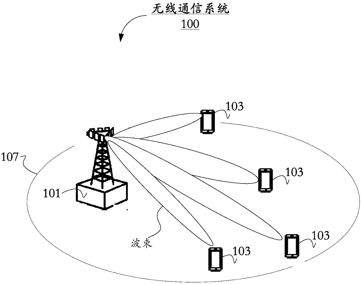
[0400] In this embodiment, the network device may send the first message (paging indication) to multiple terminals. Multiple terminals that have received the first message send uplink signals to the network device. The network device can know the beam where the paged terminal is located according to the uplink signal, and use the beam where the paged terminal is located to send a paging message.

[0401] see Figure 7A , the signal transmission method in this embodiment may include the following steps:

[0402] S101. The network device sends a first message to the terminal.

[0403] In this embodiment, the terminal may include multiple terminals within a tracking area, may also include multiple terminals within the jurisdiction of the network device, and may also include multiple terminals corresponding to one or more POs. And, the multiple terminals include at least one paged terminal.

[0404] The specific timing for sending the first message will be described below. Th...

Embodiment 2

[0420] This embodiment corresponds to the scenario grouped in the above key technical point (1).

[0421] In this embodiment, the network device may send the first configuration information and the first message to multiple terminals. The multiple terminals determine the group they belong to according to the first configuration information, and determine whether any terminal in the group they belong to is paged according to the first message. All or part of the terminals in the group including the paged terminal can send an uplink signal to the network device. The network device sends paging information according to the uplink signal.

[0422] In this embodiment, the implementation of the first message is the first implementation in the key technical point (4), and the implementation of the first configuration information is the first implementation in the key technical point (5).

[0423] see Figure 7B , the signal transmission method in this embodiment may include the fo...

Embodiment 3

[0452] The difference between this embodiment and the second embodiment is that in step S201, the network device does not need to send the first configuration information to the terminal, and step S202 is not included, and the terminal does not need to determine the group it belongs to according to the first configuration information. Other steps are all identical with embodiment two.

[0453]In this embodiment, the network device does not need to send the first configuration information to the terminal, the number of data bits in the first message, the number of groups associated with the first message, the number of data bits indicating each group in the first message, and the number of data bits used to calculate the group At least one of the number of data bits of the information, the position of the data bits used to calculate the grouping information in the terminal identifier, the number of POs, the length of the DRX cycle, or the number of synchronization signal blocks ...


PUM


Abstract

The invention provides a communication method and a communication device. The method comprises the following steps: receiving downlink control information DCI sent by a network device through a physical downlink control channel PDCCH, wherein the DCI comprises information of physical downlink shared channel PDSCH time-frequency resource blocks, and the DCI schedules N PDSCH time-frequency resourceblocks, each PDSCH time-frequency resource block provides the paging information of at least one terminal device, and the N is a positive integer greater than or equal to 1; determining the PDSCH time-frequency resource blocks needing to be demodulated according to the DCI, wherein the PDSCH time-frequency resource blocks needing to be demodulated are a part of time-frequency resource blocks among the N PDSCH time-frequency resource blocks; and modulating the PDSCH time-frequency resource blocks needing to be demodulated. Since a part of time-frequency resource blocks is demodulated, comparedwith the manner of demodulating all PDSCH time-frequency resource blocks, the power consumption overhead of the terminal device brought by the demodulation of the PDSCH time-frequency resource blocksis reduced.

Description

technical field [0001] The present application relates to the technical field of communication, and in particular to a communication method and communication device in a wireless communication system. Background technique [0002] The development of mobile services has higher and higher requirements on the data rate and efficiency of wireless communication. In future wireless communication systems, beamforming technology is used to limit the energy of transmitted signals to a certain beam direction, thereby increasing the efficiency of signals and reception. Beamforming technology can effectively expand the transmission range of wireless signals and reduce signal interference, thereby achieving higher communication efficiency and higher network capacity. However, in a communication network using beamforming technology, it is first necessary to match the sending beam with the receiving beam to maximize the gain from the sending end to the receiving end, otherwise relatively ...

Claims


Application Information

Patent Timeline
IPC IPC(8): H04W72/04H04L5/00
CPCH04L5/0053H04W72/23H04L5/00H04W72/04Y02D30/70
Inventor 高宽栋李赛楠黄煌
Owner HUAWEI TECH CO LTD
Why Eureka
Try Eureka