Method and System for User Equipment Location Determination on a Wireless Transmission System

a wireless transmission system and user equipment technology, applied in the field of wireless communication techniques, can solve the problems of degraded signal quality, limited available spectrum for wireless services, increased interference in the system, etc., and achieve the effects of low cost, and improving neighbor cell hearability

Active Publication Date: 2011-11-24
APPLE INC
View PDF5 Cites 124 Cited by
  • Summary
  • Abstract
  • Description
  • Claims
  • Application Information

AI Technical Summary

Benefits of technology

[0026]Neighbor cell hearability can be improved by including an additional reference signal that can be detected at a low sensitivity and a low signal-to-noise ratio, by introducing non-unity frequency reuse for the signals used for a time difference of arrival (TDOA) measurement, e.g., orthogonality of signals transmitted from the serving cell sites and the various

Problems solved by technology

The available spectrum for wireless services is limited, however, and the prior attempts to increase traffic within a fixed bandwidth have increased interference in the system and degraded signal quality.
Technologies like multiple input multiple output (MIMO), orthogonal frequency division multiplexing (OFDM), and advanced error control codes enhance per-link throughput, but these technologies do not solve all problems encountered in the communication network.
One problem encountered in neighbor cell hearability arises when user equipment is located near to the center of the serving cell site such that reference signals from neighbor cell sites are too weak for proper detection by the user equipment.
In this situation, the reference signals from neighbor cell sites is too weak for the user equipment to accurately estimate the time difference of arrivals between the reference signal from the serving and various neighbor cell sites, which hinders

Method used


Image

  • Method and System for User Equipment Location Determination on a Wireless Transmission System
  • Method and System for User Equipment Location Determination on a Wireless Transmission System
  • Method and System for User Equipment Location Determination on a Wireless Transmission System

Examples


Embodiment Construction

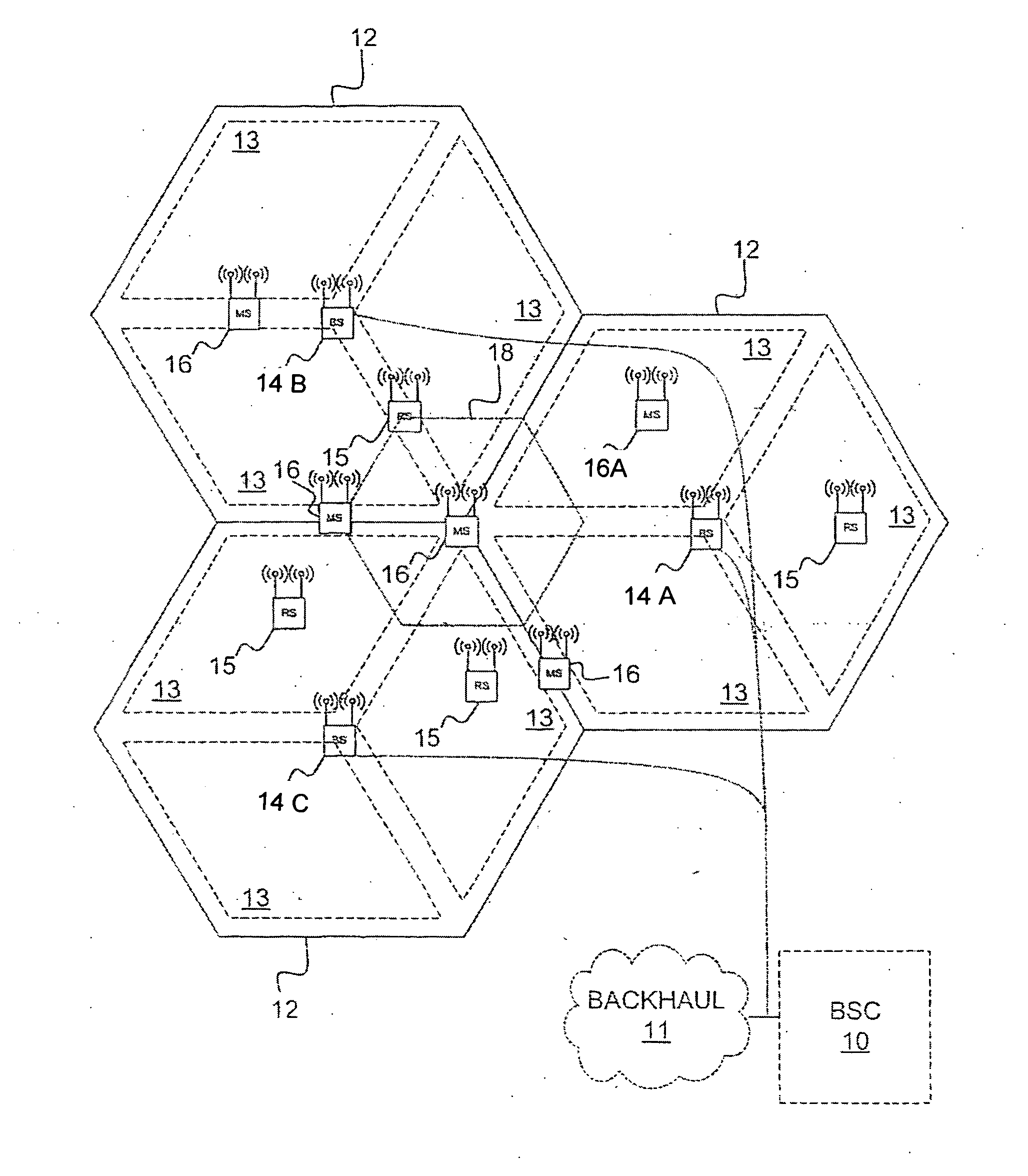
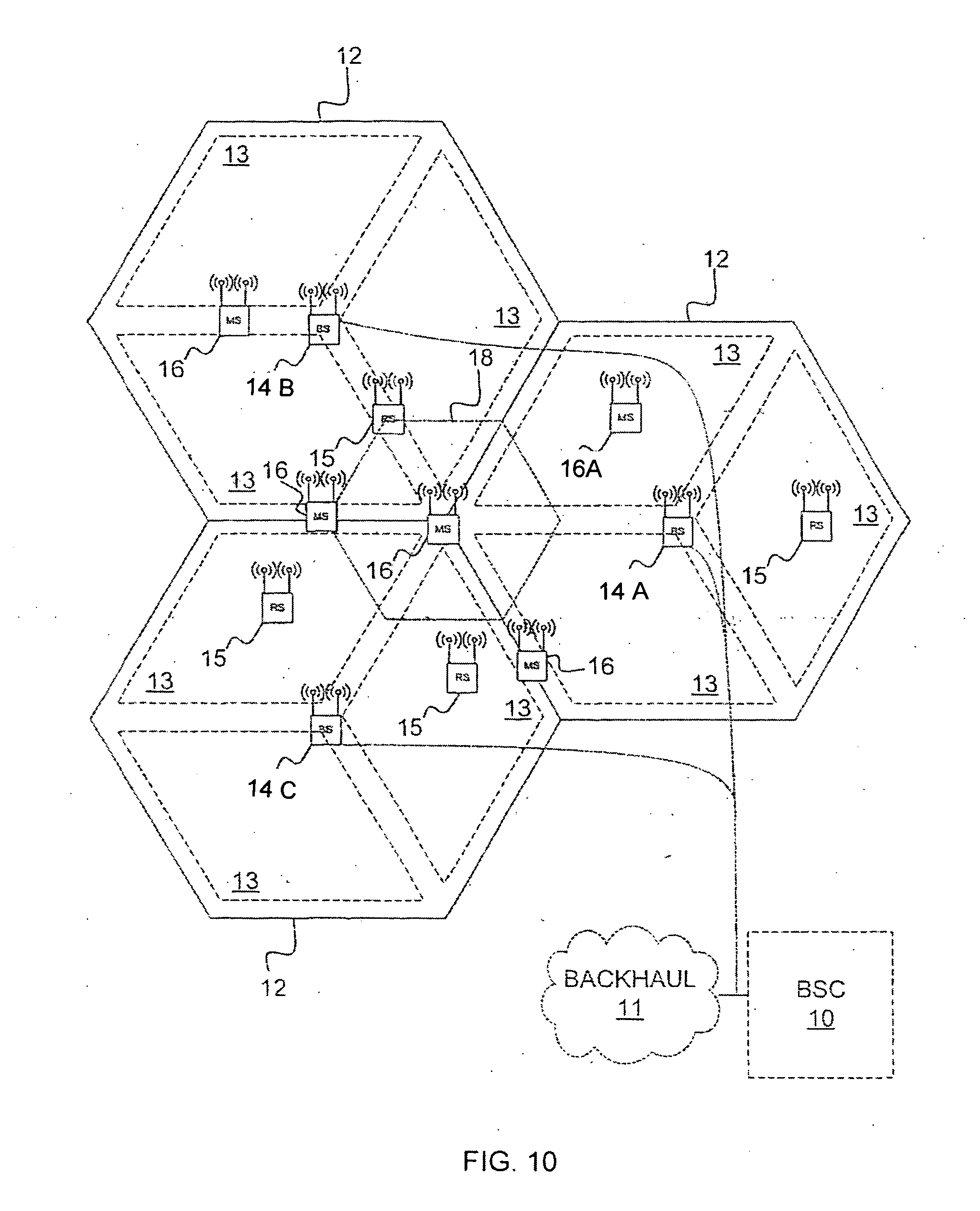
[0034]Referring to FIG. 8, the block diagram shows a base station controller (BSC) 10 which controls wireless communications within multiple cells 12, which cells are served by corresponding basestations (BS) 14. In some configurations, each cell is further divided into multiple sectors 13 or zones. In general, each base station 14 facilitates communications using OFDM with mobile and / or wireless terminals 16, which are within the cell 12 associated with the corresponding base station 14. The movement of the mobile terminals 16 in relation to the base stations 14 results in significant fluctuation in channel conditions.

[0035]As illustrated, the base stations 14 and mobile terminals 16 may include multiple antennas to provide spatial diversity for communications. In some configurations, relay stations 15 may assist in communications between base stations 14 and wireless terminals 16. Wireless terminals 16 can be handed from any cell 12, sector 13 zone, base station 14 or relay 15 to ...


PUM


Abstract

Neighbor cell hearability can be improved by including an additional reference signal that can be detected at a low sensitivity and a low signal-to-noise ratio, by introducing non-unity frequency reuse for the signals used for a time difference of arrival (TDOA) measurement, e.g., orthogonality of signals transmitted from the serving cell sites and the various neighbor cell sites. The new reference signal, called the TDOA-RS, is proposed to improve the hearability of neighbor cells in a cellular network that deploys 3GPP EU-TRAN (LTE) system, and the TDOA-RS can be transmitted in any resource blocks (RB) for POSCH and/or MBSFN subframe, regardless of whether the latter is on a carrier supporting both PMCH and POSCH or not. Besides the additional TDOA-RS reference signal, an additional synchronization signal (TDOA-sync) may also be included to improve the hearability of neighbor cells.

Description

CROSS-REFERENCE TO RELATED APPLICATIONS[0001]This application is related to Provisional Patent Applications Ser. Nos. 61 / 150,137 filed on Feb. 5, 2009, 61 / 168,087 filed on Apr. 9, 2009, and 61 / 174,333 filed on Apr. 30, 2009, and priority is claimed for these earlier filings under 35 U.S.C. § 119(e). These Provisional Patent Applications are incorporated by reference into this utility patent application.TECHNICAL FIELD OF THE INVENTION[0002]This application relates to wireless communication techniques in general, and to determining position of user equipment using positioning reference signals in particular.BACKGROUND OF THE INVENTION[0003]There is an increasing demand on mobile wireless operators to provide voice and high-speed data services, and at the same time, mobile network operators wish to support more users per basestation to reduce overall network costs and make services more affordable to subscribers. As a result, wireless systems that enable higher data rates and higher c...

Claims


Application Information

Patent Timeline
IPC IPC(8): H04W24/00H04W4/02
CPCH04W64/00H04W4/02G01S5/10H04W24/10H04W56/0015H04W56/0045H04W72/0446H04L5/0007H04W72/30G01S11/08H04B7/2603H04J11/0023G01S1/24H04B1/713H04L5/005H04W4/06
Inventor TEE, LAI KINGWU, GENGLI, JUNTANG, YUQIANGWANG, NENGXU, HUAMA, JIANGLEI
Owner APPLE INC
Why Eureka
Try Eureka