
Control Device for Internal Combustion Engine

Active Publication Date: 2016-04-28
TOYOTA JIDOSHA KK
View PDF15 Cites 6 Cited by
  • Summary
  • Abstract
  • Description
  • Claims
  • Application Information

AI Technical Summary

Benefits of technology

The invention is a device that can control the engine's combustion state to minimize fuel consumption and improve engine sound quality. The device measures the position of the engine's center of gravity and uses this information to maintain the combustion state in a specific state, regardless of changes in load and rotational speed. This results in improved fuel efficiency and reduced fuel consumption. The device also controls the waveform of the engine's sound to enhance its audibility.

Problems solved by technology

In general, energy resulting from the combustion of an air-fuel mixture when an internal combustion engine (hereinafter, also referred to as an “engine”) such as a diesel engine is in operation inevitably leads to losses, without being fully converted into work rotating a crankshaft.
These losses include a cooling loss that is converted into a rise in engine main body and cooling water temperatures, an exhaust loss that is released to the atmosphere by exhaust gas, a pump loss that results during air intake and exhaust, and a mechanical resistance loss.
The cooling loss and the exhaust loss account for large portions of the entire loss.
However, the cooling loss and the exhaust loss have a trade-off relationship in general, and thus it is difficult to reduce the cooling loss and the exhaust loss at the same time in many cases.
However, an actual improvement in compression rate causes a combustion temperature to increase, and thus the cooling loss increases.
However, it is difficult to have a plurality of the combustion parameters obtained in advance by an experiment or the like as values optimal for the respective operation states, and a large-scale experiment needs to be carried out in order to determine these combustion parameters.

Method used


Image

  • Control Device for Internal Combustion Engine
  • Control Device for Internal Combustion Engine
  • Control Device for Internal Combustion Engine

Examples


Embodiment Construction

[0138]A control device for an internal combustion engine according to an embodiment of the invention (hereinafter, also referred to as “this control device”) will be described with reference to accompanying drawings. This control device is applied to an engine 10 that is illustrated in FIG. 4. The engine 10 is a multi-cylinder (four-cylinder) diesel engine.

[0139]Fuel injection valves (injectors) 20 are arranged in upper portions of respective cylinders of the engine 10. A fuel pressure pump (supply pump) 21 supplies fuel that is stored in a fuel tank (not illustrated) to an accumulator (common rail) 22 in a high-pressure state. The fuel injection valves 20 inject the fuel in the accumulator 22 into the cylinders at a timing indicated by an engine ECU 70 (described later).

[0140]An intake manifold 30 that is connected to each of the cylinders and an intake pipe 31 that is connected to an upstream collecting portion of the intake manifold 30 constitute an intake passage.

[0141]A throttl...


PUM


Abstract

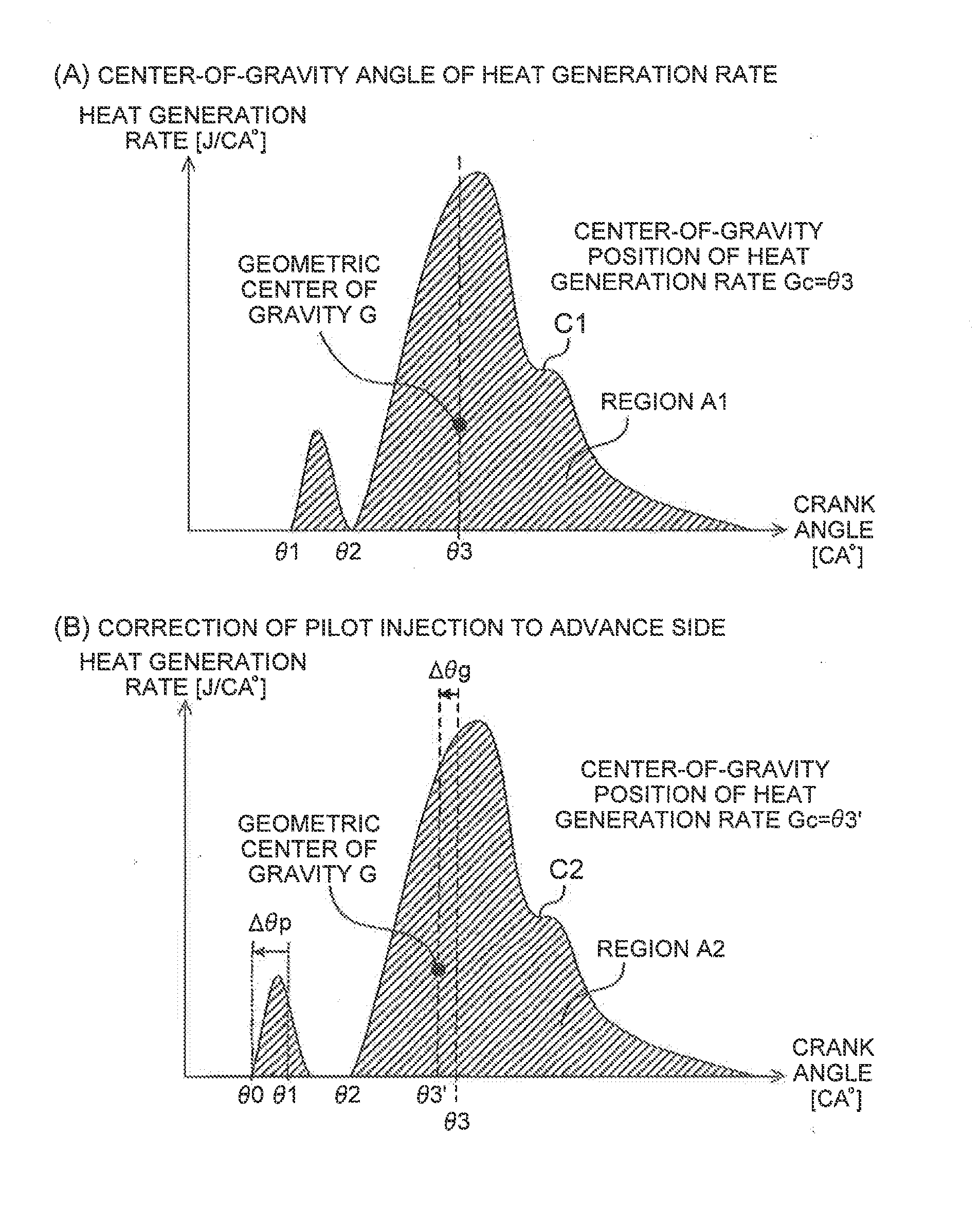
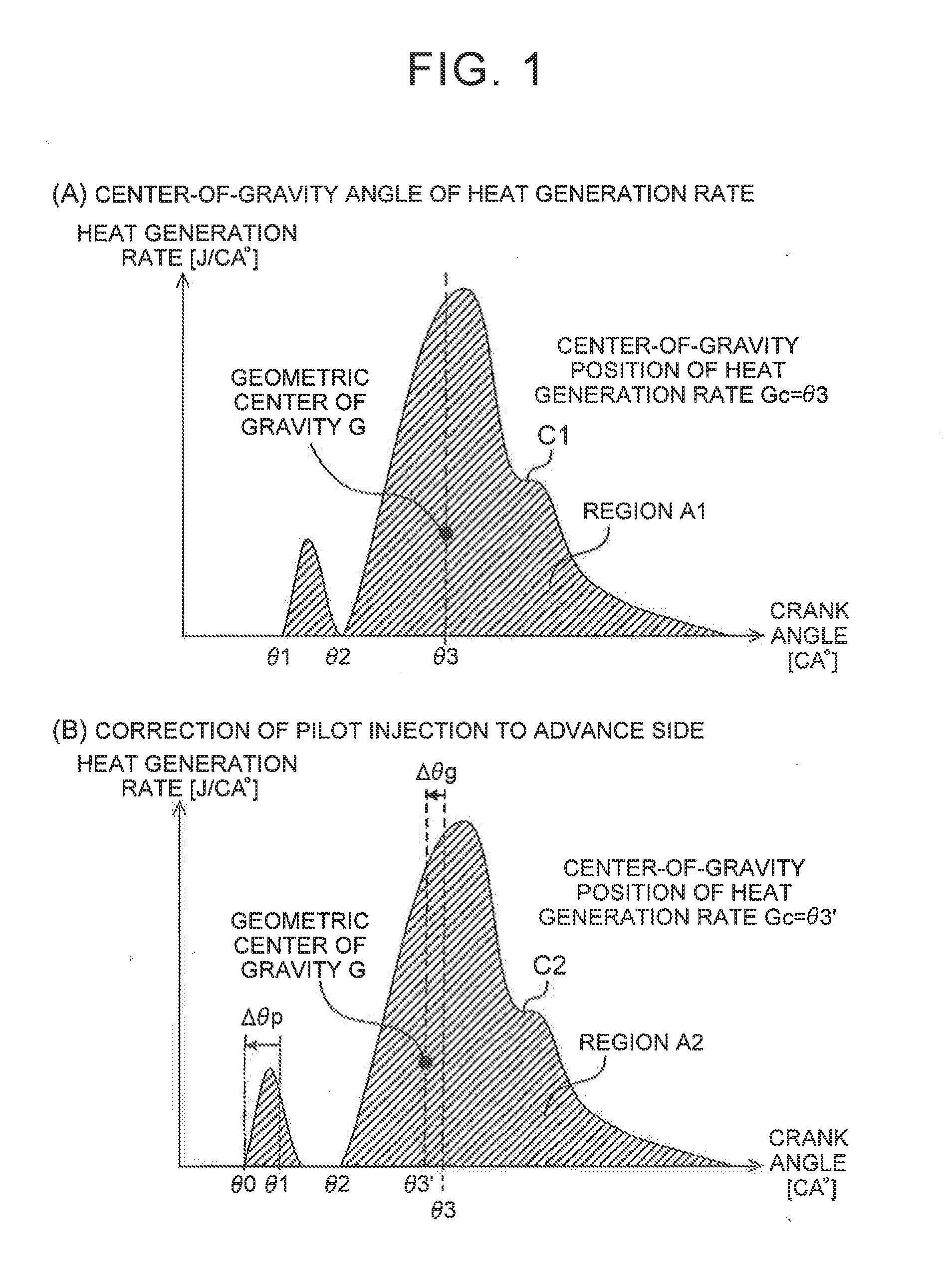
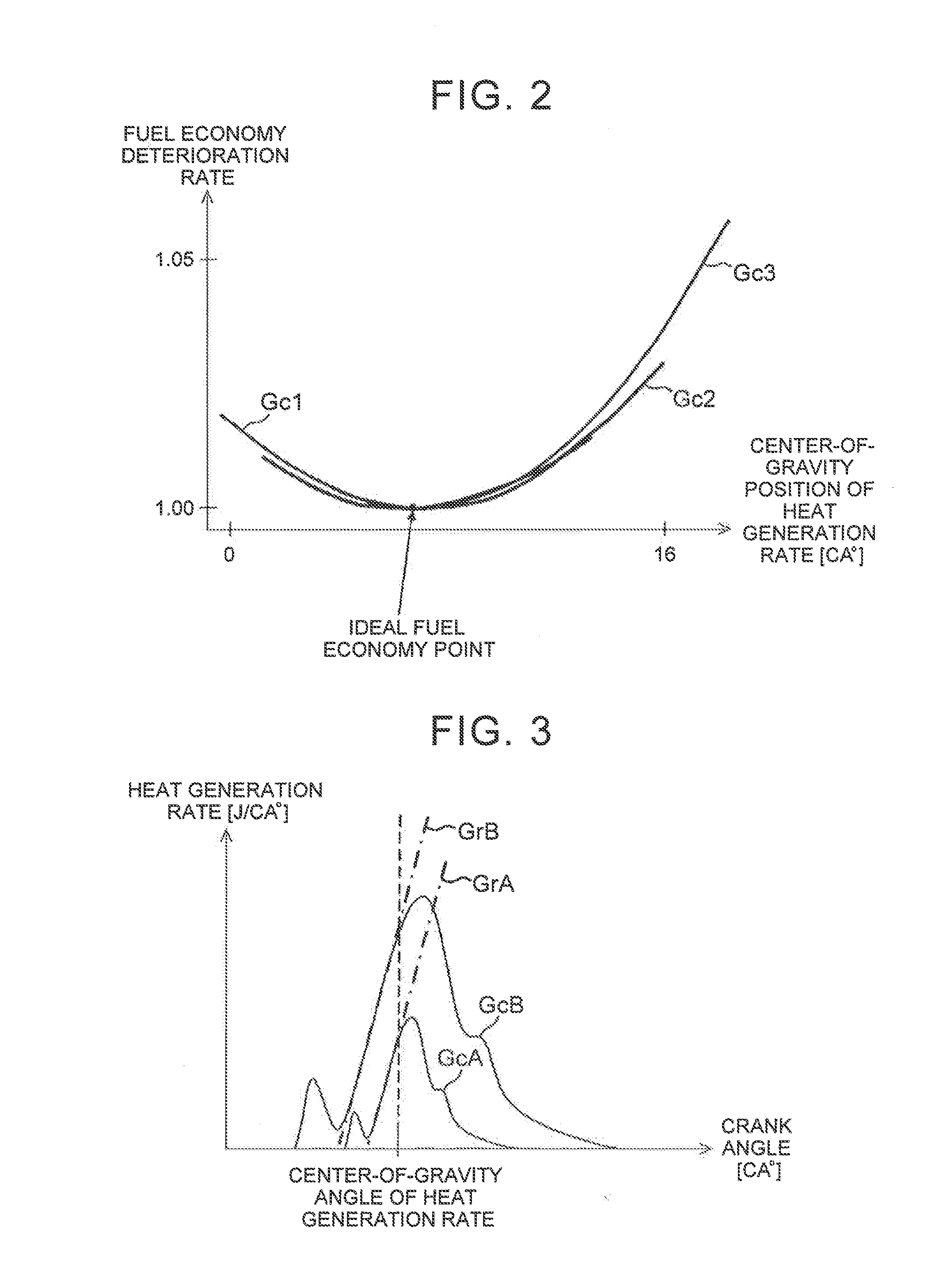
To provide a control device capable of setting a plurality of combustion parameters changing a combustion state of an internal combustion engine to appropriate values and improving a fuel consumption rate regardless of an operation state.An engine ECU 70 sets a combustion parameter (main injection timing, pilot injection timing, fuel injection pressure, turbocharging pressure, or the like) such that a center-of-gravity position of a heat generation rate becomes a constant target crank angle regardless of a load of an engine 10. In addition, the ECU 70 estimates the center-of-gravity position of a heat generation rate based on an output of an in-cylinder pressure sensor 64 and feedback-controls the combustion parameter such that the estimated center-of-gravity position of a heat generation rate becomes equal to the target crank angle.

Description

TECHNICAL FIELD[0001]The invention relates to a control device that controls a combustion state of an internal combustion engine.BACKGROUND ART[0002]In general, energy resulting from the combustion of an air-fuel mixture when an internal combustion engine (hereinafter, also referred to as an “engine”) such as a diesel engine is in operation inevitably leads to losses, without being fully converted into work rotating a crankshaft. These losses include a cooling loss that is converted into a rise in engine main body and cooling water temperatures, an exhaust loss that is released to the atmosphere by exhaust gas, a pump loss that results during air intake and exhaust, and a mechanical resistance loss. The cooling loss and the exhaust loss account for large portions of the entire loss. Accordingly, it is effective to decrease the cooling loss and the exhaust loss when the fuel consumption rate of the engine is to be improved.[0003]However, the cooling loss and the exhaust loss have a t...

Claims


Application Information

Patent Timeline
IPC IPC(8): F02D41/04
CPCF02D41/04F02D35/023F02D35/026F02D35/028
Inventor YAMASHITA, AKIRAIWATA, KAZUYASU
Owner TOYOTA JIDOSHA KK
Learn More