Base station, communication terminal, transmission method, and reception method

a communication terminal and base station technology, applied in the field of wireless communication technologies, can solve the problems of increasing the workload of signal processing at the sending and receiving end, reducing resource utilization efficiency, and difficulty in further improving reception quality, so as to achieve efficient transmission of control channels

Active Publication Date: 2010-04-29
NTT DOCOMO INC
View PDF4 Cites 121 Cited by
  • Summary
  • Abstract
  • Description
  • Claims
  • Application Information

AI Technical Summary

Benefits of technology

[0009]An aspect of the present invention makes it possible to efficiently transmit control channels to communication terminals in a communication system where a frequency band allocat

Problems solved by technology

However, with this method, it is difficult to further improve the reception quality.
However, using a variable format may increase the signal processing workload at the sending and receiving ends.
In this case, even if a control channel occupies only a part of the control c

Method used


Image

  • Base station, communication terminal, transmission method, and reception method
  • Base station, communication terminal, transmission method, and reception method
  • Base station, communication terminal, transmission method, and reception method

Examples


first embodiment

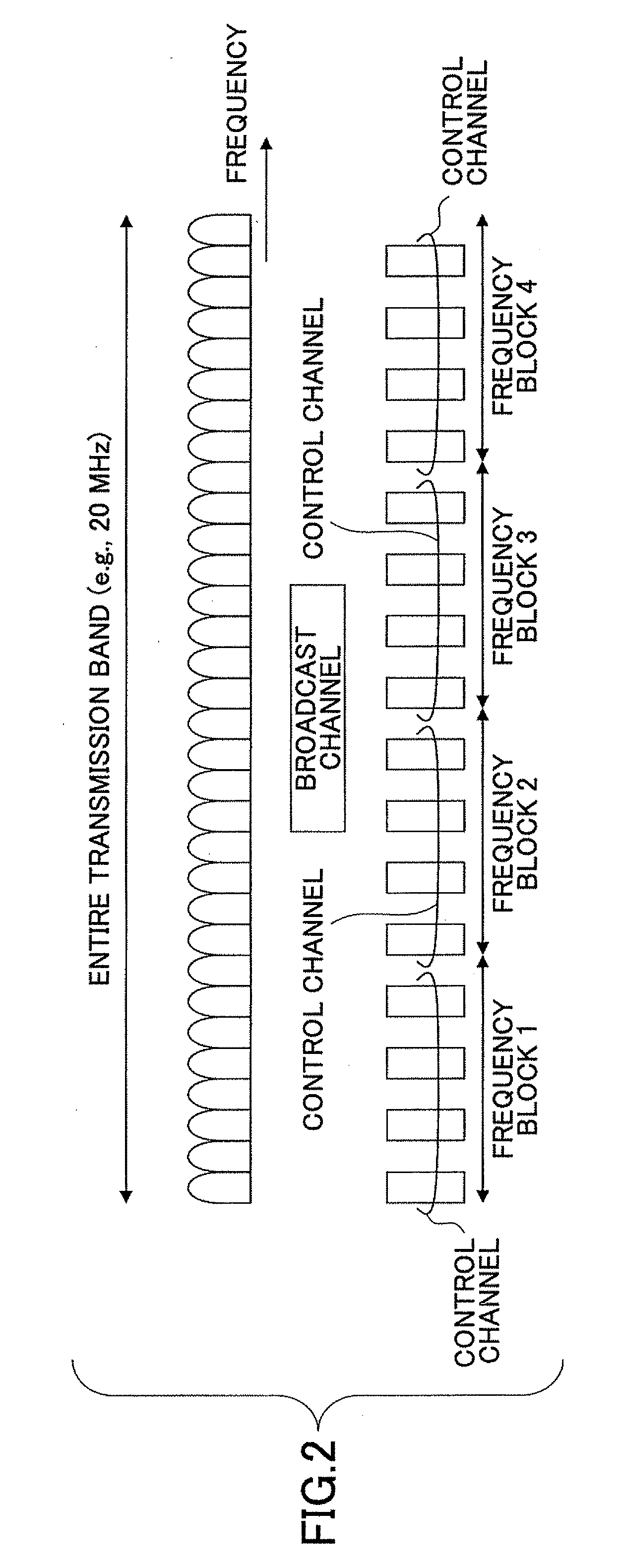
[0087]FIG. 2 is a drawing illustrating a frequency band used in an embodiment of the present invention. Values used in the descriptions below are just examples and different values may be used. In this example, a frequency band (entire transmission band) allocated to a communication system has a bandwidth of 20 MHz. The entire transmission band includes four frequency blocks 1 through 4. Each of the frequency blocks includes multiple resource blocks each including one or more subcarriers. FIG. 2 schematically shows frequency blocks each including multiple subcarriers. In this embodiment, it is assumed that four different communication bandwidths of 5 MHz, 10 MHz, 15 MHz, and 20 MHz are defined. A user device (e.g., a communication terminal, a mobile terminal, or a fixed terminal) performs communications using one or more frequency blocks in one of the four bandwidths. A communication terminal in the communication system may support all of the four bandwidths or support only part of ...

second embodiment

[0209]Since the general control channel (including part 0) is information necessary for all users and is used to decode data channels, error detection (CRC) coding and channel coding are performed on the general control channel. In a second embodiment of the present invention, exemplary methods of error detection coding and channel coding are described. In the configuration of FIG. 4B, it is assumed that L1 / L2 control information (part 0) and L1 / L2 control information (parts 2a and 2b) are channel-coded separately (i.e., channel-coding / spreading / data-modulation units 41 and 42-A are provided, respectively, for part 0, part 2a, and part 2b). Variations of this configuration are described below.

[0210]FIG. 10A illustrates a method where part 0 and parts 2a and 2b are error-detection-coded together but are channel-coded separately. In this case, each of communication terminals UE1 and UE2 performs error detection collectively on part 0 and parts 2a and 2b, and extracts an L1 / L2 control ...

third embodiment

[0215]To improve the received signal quality of control channels, it is preferable to perform link adaptation. In a third embodiment of the present invention, transmission power control (TPC) and adaptive modulation and coding (AMC) are used to perform link adaptation. FIG. 11 is a drawing illustrating an example of transmission power control where transmission power of downlink channels is controlled to achieve desired reception quality. Referring to FIG. 11, a high transmission power level is used to transmit a downlink channel to user 1 because user 1 is away from the base station and its channel conditions are expected to be poor. Meanwhile, channel conditions of user 2 close to the base station are expected to be good. In this case, using a high transmission power level to transmit a downlink channel to user 2 may increase the received signal quality at user 2 but may also increase interference with other users. Because the channel conditions of user 2 are good, it is possible ...


PUM


Abstract

A base station includes a scheduler configured to perform frequency scheduling for each subframe; a control channel generating unit configured to generate a control channel including common control information to be mapped to radio resources distributed across a system frequency band and specific control information to be mapped to one or more resource blocks allocated to each selected user device; and a transmission signal generating unit configured to generate a transmission signal by time-division-multiplexing the common control information and the specific control information according to scheduling information from the scheduler. The common control information includes a format indicator representing one of preset options that indicates the number of symbols occupied by the common control information in one subframe. The common control information includes information units with a predetermined data size. The number of the information units is less than or equal to a specified multiplicity included in broadcast information.

Description

TECHNICAL FIELD[0001]The present invention generally relates to wireless communication technologies. More particularly, the present invention relates to a base station, a communication terminal, a transmission method, and a reception method used in a communication system where frequency scheduling and multicarrier transmission are employed.BACKGROUND ART[0002]In the field of wireless communication, there is a growing demand for a broadband wireless access system that enables efficient, high-speed, high-volume communications. For downlink in such a system, a multicarrier scheme such as orthogonal frequency division multiplexing (OFDM) is expected to be used to achieve high-speed, high-volume communications while effectively restraining multipath fading. Also, in next generation systems, use of frequency scheduling is proposed to improve the frequency efficiency and thereby to increase the throughput.[0003]As shown in FIG. 1, in next generation systems, a system frequency band is divi...

Claims


Application Information

Patent Timeline
IPC IPC(8): H04W72/00H04K1/10H04J99/00H04W68/00H04W72/04H04W88/08
CPCH04L1/0004H04W88/08H04L1/0015H04L1/0028H04L1/0038H04L1/0061H04L1/007H04L5/0016H04L5/0023H04L5/0041H04L5/0044H04L5/0053H04L5/0094H04L25/03343H04L2025/03414H04W68/00H04W72/042H04L1/001H04L1/0003H04L1/0009H04L1/1812H04L5/0007H04L27/2602H04L27/2626H04W72/23H04W72/12H04W88/02
Inventor MIKI, NOBUHIKOHIGUCHI, KENICHISAWAHASHI, MAMORU
Owner NTT DOCOMO INC
Why Eureka
Try Eureka