Headpiece having root canal length measurement function

A technology of length measurement and root canal, used in dentistry, prosthodontics, dental drilling, etc., which can solve the problem of not using handpieces

Inactive Publication Date: 2002-11-27
MORITA MFG CO LTD
View PDF9 Cites 2 Cited by
  • Summary
  • Abstract
  • Description
  • Claims
  • Application Information

AI Technical Summary

Problems solved by technology

This cutting and digging tool cannot be used with the nose mentioned above

Method used


Image

  • Headpiece having root canal length measurement function
  • Headpiece having root canal length measurement function
  • Headpiece having root canal length measurement function

Examples


Embodiment Construction

[0022] An embodiment of the present invention will be described below. This embodiment relates to a cordless handpiece in which a motor, a power supply battery, a root canal length measurement circuit, etc. are incorporated in the main unit. However, the present invention is not limited to such a cordless type, but can be applied to a type of handpiece in which motor transmission power, etc. are supplied by an independent control device through a tube. At this time, the root canal length measurement circuit can also be installed in an independent control unit, and the signal circuit is connected to the root canal length measurement circuit through a tube.

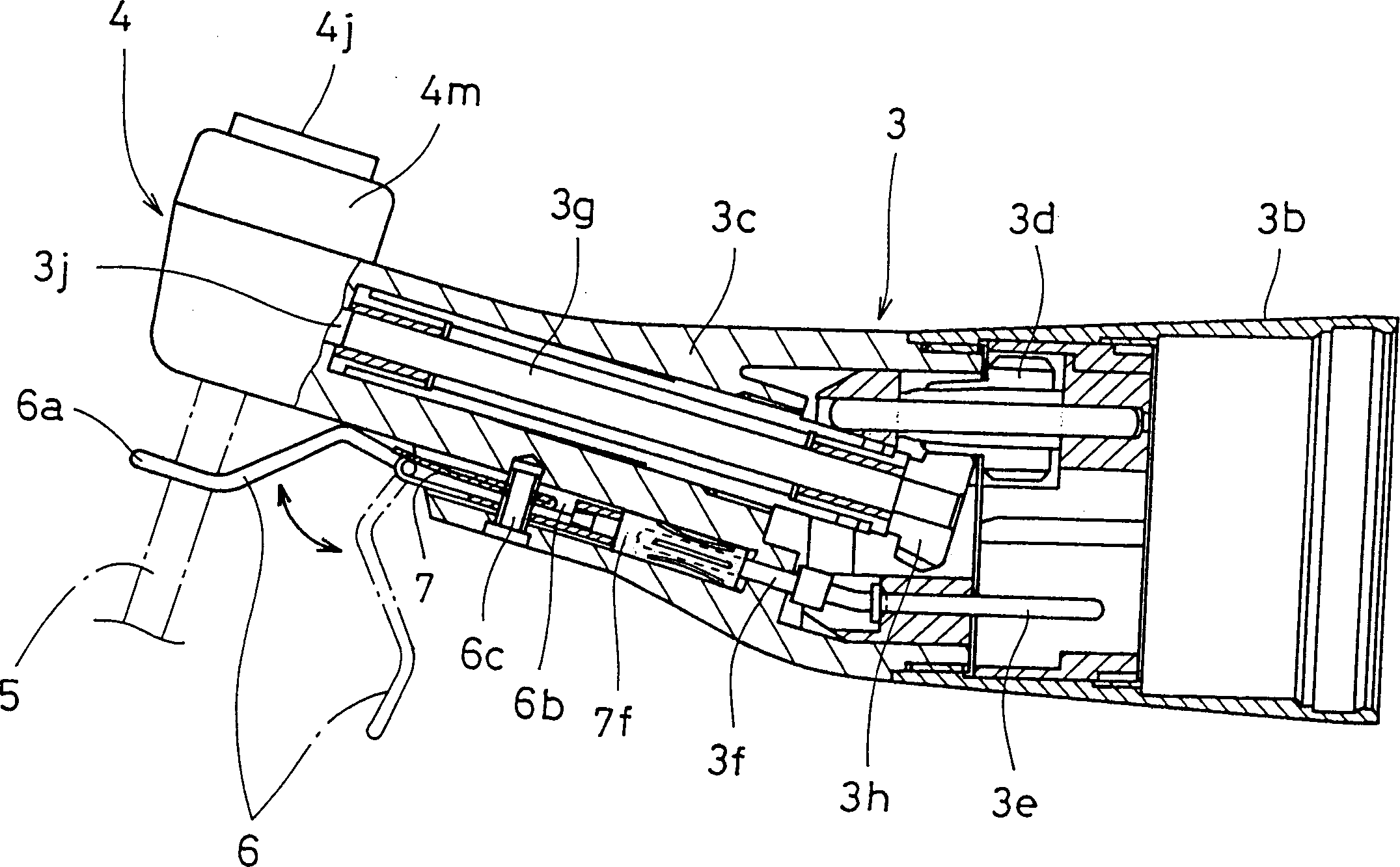
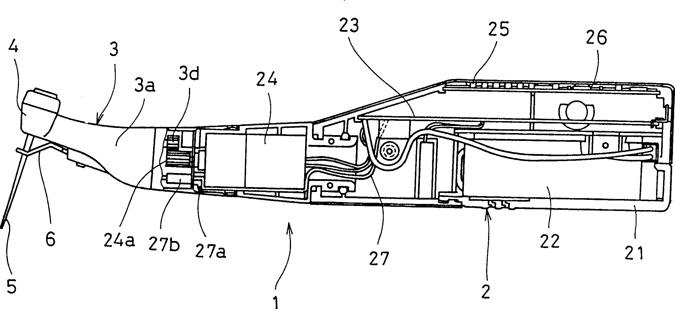
[0023] Referring to the accompanying drawings, numeral 1 represents a head, which is composed of a head main unit 2 and a head 3 . The head unit 3 is mounted on the end of the head main unit 2 . The case 21 of the handpiece main unit 2 houses a battery 22, a printed circuit board 23, a motor 24, and the like. The upper p...


PUM


Abstract

The invention discloses a machine head with the function of measuring the length of the root canal, wherein the signal circuit is specially arranged for sending the measurement signal from the root canal length measuring circuit to the measuring probe mounted on the head located at the top of the machine head , which is placed in the handpiece and is electrically connected to the measuring probe through contacts near the measuring probe. Therefore, there is no need to connect signal circuits externally to the handpiece for measurement. In addition, this structure improves handpiece workability since there are no leads for connection. Moreover, this structure eliminates the trouble of connecting external leads to the head of the handpiece. Furthermore, it is possible to use a cutting tool with a tail and a cutting portion which are insulated from each other.

Description

technical field [0001] The invention relates to the improvement of the machine head with the function of measuring the length of the root canal on the dental treatment equipment. Background technique [0002] A device is known which allows root canal treatment and simultaneous measurement of the root canal, using an excavation tool, such as a file or a drill, which is also used as a measuring probe. In this case, since the cutting and digging tool is used as an electrode of the root canal length measurement circuit, the measurement signal needs to be transmitted to the cutting and digging tool by the lead wire. Such leads are usually connected via the exterior of the device head. This causes the problem of weakening the workability of the handpiece because of the hindrance of the lead wires, and also brings the troublesome problem that the lead wires must be connected to the head of the handpiece externally for each treatment, (seeing Japanese Patent JP5064643A for example)...

Claims


Application Information

Patent Timeline
Patent Type & Authority Patents(China)
IPC IPC(8): A61C1/08A61C1/14A61C19/04
CPCA61C1/08A61C1/14A61C19/041A61C2204/002
Inventor 中山照三吉田雅信日下部博昭的场一成
Owner MORITA MFG CO LTD
Why Eureka
Try Eureka