
Submarine drive system

A technology for driving systems and submarines, which can be applied to ships, motor vehicles, underwater ships, etc., can solve problems such as efficiency disadvantages, and achieve the effect of cost-effectiveness and avoiding efficiency disadvantages.

Pending Publication Date: 2019-03-15
RENCK GMBH
View PDF11 Cites 1 Cited by
  • Summary
  • Abstract
  • Description
  • Claims
  • Application Information

AI Technical Summary

Problems solved by technology

Leads to efficiency disadvantages especially during part load operation
Furthermore, relatively large motors have to be used

Method used


Image

  • Submarine drive system
  • Submarine drive system
  • Submarine drive system

Examples


Embodiment Construction

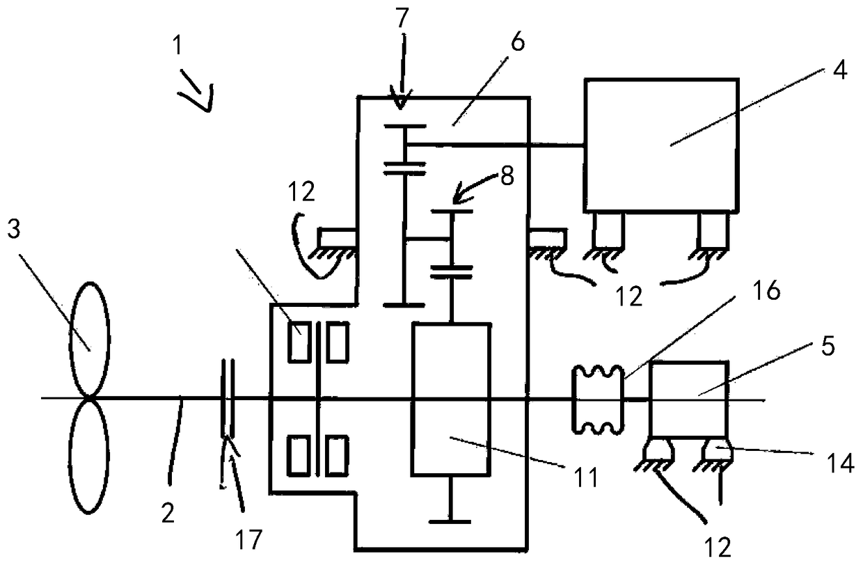
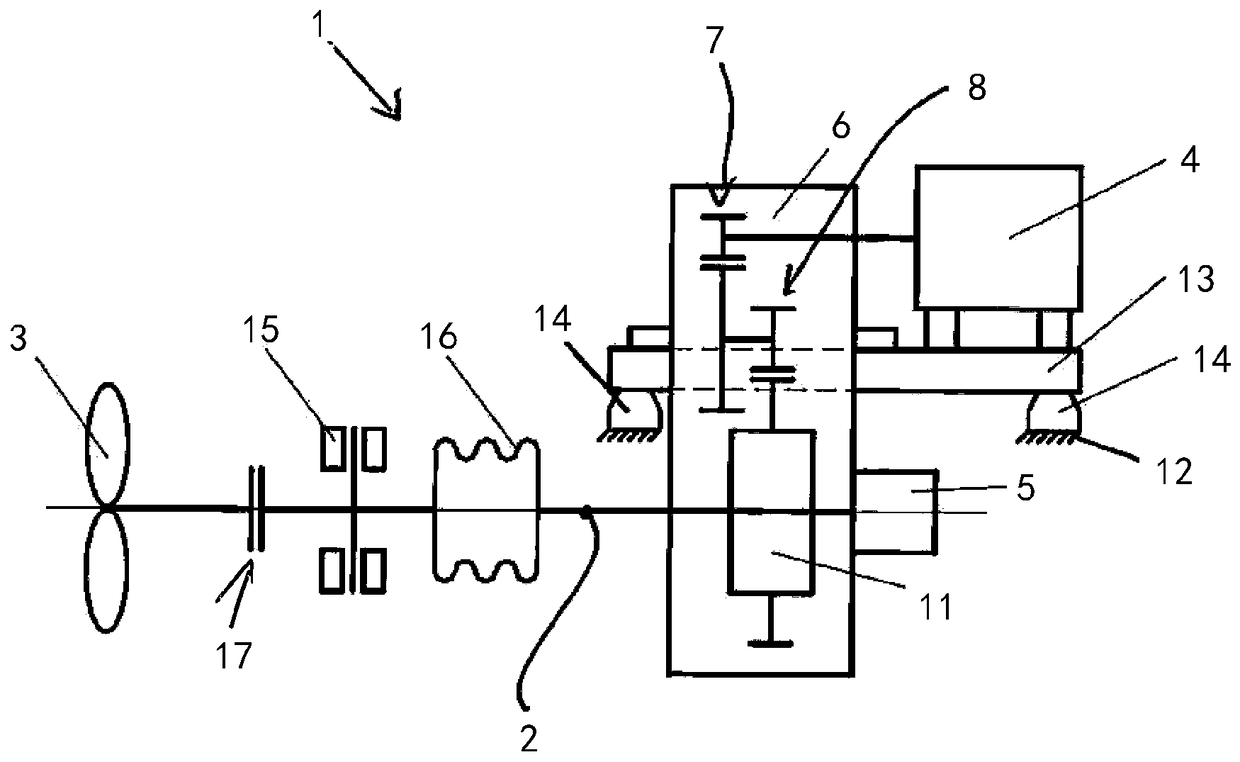
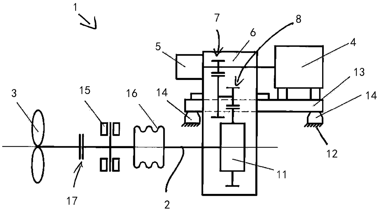
[0017] Figure 1 to Figure 5 Different exemplary embodiments of a submarine drive system 1 according to the invention are shown. Figure 1 to Figure 5 Common to all submarine drive systems 1 is that they include a drive shaft 2, a drive propeller 3 coupled to the drive shaft 2, and a plurality of electric motors 4,5. The at least one first electric motor 4 of the main drive for driving the drive shaft 2 and thus the propeller 3 is designed for full-load operation of the submarine drive system and is coupled or can be coupled to the drive shaft 2 on the drive side . The additionally driven at least one second electric machine 5 is designed for part-load operation of the submarine drive system 1 and is likewise coupled or can be coupled to the drive shaft 2 on the drive side, wherein in the part of the submarine drive system 1 During on-load operations, the submarine typically operates in stealth mode and / or underwater mode.

[0018] Thus, the idea of ​​the submarine drive sy...


PUM


Abstract

The invention relates to a submarine drive system (1) of a submarine, comprising a drive shaft (2), comprising a drive propeller (3) coupled to the drive shaft (2), comprising an electric motor (4, 5)for driving the drive shaft (2), wherein a main drive having at least one first electric motor (4) is designed for full-load operation and is or can be coupled to the drive shaft on the drive side, and wherein an additional drive having at least one second electric motor (5) is designed for part-load operation for creep operation or submerged operation of the submarine and likewise is or can be coupled to the drive shaft on the drive side.

Description

technical field [0001] The invention relates to a submarine driving system. Background technique [0002] Submarine drive systems are known, comprising a drive shaft, comprising a drive thruster coupled to the drive shaft, and comprising an electric motor for driving the drive shaft. Here, the electric motor of the submarine drive system is conventionally coupled directly to the drive shaft. Here, the electric machine is used for full load operation and also for part load operation. This leads to efficiency disadvantages especially during part load operation. Furthermore, relatively large motors have to be used. [0003] A drive system for a ship is known from DE 10 2012 208 065 A1, in which case an electric machine is directly or indirectly coupled to a drive shaft via a transmission. By connecting a transmission between the electric motor and the drive shaft, it is possible to use smaller, Lighter and more cost-effective motors. Contents of the invention [0004] P...

Claims


Application Information

Patent Timeline
Patent Type & Authority Applications(China)
IPC IPC(8): B63G8/08
CPCB63G8/08B63H2023/245B63G8/34B63H21/17B63H23/24
Inventor B.平内坎普T.克莱因海恩茨D.维特金德F.霍佩T.施密德鲍尔B.福尔默
Owner RENCK GMBH
Learn More