High pressure exhaust gas recirculation system with heat recovery

A technology of exhaust gas recirculation and recirculation system, applied in the direction of exhaust gas recirculation, charging system, electrical control, etc., can solve the problems of large installation space and achieve the effect of high exhaust gas flow rate

Inactive Publication Date: 2016-09-07
FORD GLOBAL TECH LLC
View PDF5 Cites 0 Cited by
  • Summary
  • Abstract
  • Description
  • Claims
  • Application Information

AI Technical Summary

Problems solved by technology

[0011] The two systems, that is to say the exhaust gas recirculation system and the heat recovery system, together with their components, are provided separately, which requires a considerable installation space and can therefore only be used in a limited range or in motor vehicles superior

Method used


Image

  • High pressure exhaust gas recirculation system with heat recovery

Examples


Embodiment Construction

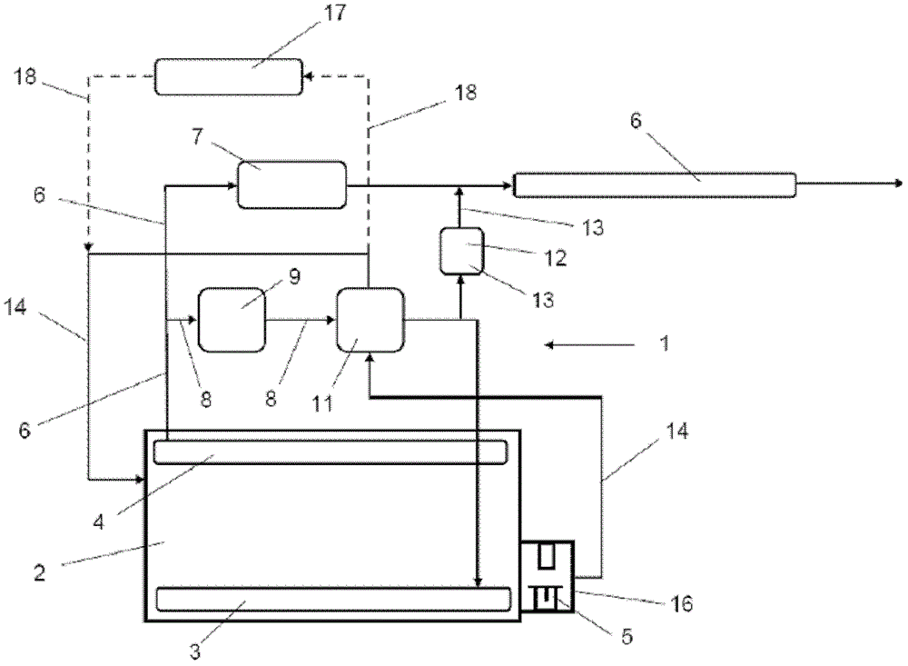
[0026] figure 1 A schematic diagram of a high-pressure exhaust gas recirculation system 1 of an internal combustion engine 2 is shown in the example of a diesel engine. In the description of the present invention, "internal combustion engine" also includes, for example, spark ignition engines or hybrid engines.

[0027] The internal combustion engine 2 has a fresh air side or inlet side 3 and an outlet or exhaust gas side 4 , and the internal combustion engine 2 has a cooling system (not shown) with a heat exchanger. This is only shown by way of example with the temperature regulator 5 in the cooling system.

[0028] Extending from the exhaust side 4 is an exhaust gas line 6 which can be connected to an exhaust gas aftertreatment device (not shown), for example in the form of a particle filter and / or a catalytic converter. The internal combustion engine 2 includes a turbocharger, of which only the turbine 7 is shown. The turbine 7 is mounted on the exhaust pipe 6 and is prefe...


PUM


Abstract

The invention relates to a high-pressure exhaust gas recirculation system (1) of an internal combustion engine, especially a diesel engine. An exhaust gas recirculation pipe (8) branches from an exhaust gas pipe (6) located upstream of a turbocharger, wherein an exhaust gas recirculation valve (9) Mounted on this EGR pipe upstream of the EGR cooler (11) and open to the fresh air side (3) of the internal combustion engine (2). It is suggested that the connecting pipe (13) is branched from the exhaust gas recirculation pipe (8) and located downstream of the exhaust gas recirculation cooler (11), and opens towards the exhaust gas pipe (6), and the control element (12) is installed on the connecting pipe (13), said exhaust gas recirculation cooler (11) is connected to the cooling system of the internal combustion engine (2). The high-pressure exhaust gas recirculation system (1) combines the advantages of exhaust gas recirculation and heat recovery, wherein in one aspect of the present invention, the high-pressure exhaust gas recirculation system (1) can be controlled so that even when the exhaust gas recirculation or recirculated exhaust gas When cooling is not actually required, the exhaust gas flow flows through said EGR cooler (11), thus making it possible to use the heat inherent in the exhaust gas to influence the warm-up phase and selectively supply said heat to the cab heating (17 ).

Description

technical field [0001] The invention relates to a high pressure exhaust gas recirculation system of an internal combustion engine, especially a diesel engine, the exhaust gas recirculation pipe is branched from the exhaust gas pipe upstream of the turbocharger, wherein the exhaust gas recirculation valve is installed in the exhaust gas upstream of the exhaust gas recirculation cooler on the recirculation line and the exhaust gas recirculation line is open on the fresh air side of the internal combustion engine. The invention also relates to a method for controlling a high-pressure exhaust gas recirculation system. Background technique [0002] Exhaust gas recirculation systems are used in internal combustion engines to reduce emissions such as nitrogen oxides from the internal combustion engine. The recirculated exhaust gas is cooled by an exhaust gas cooler to further reduce nitrogen oxide (NOx) emissions. [0003] In high-pressure exhaust gas recirculation, the exhaust g...

Claims


Application Information

Patent Timeline
Patent Type & Authority Patents(China)
IPC IPC(8): F02D41/00F02D41/06F02B37/18F02D21/08F02M26/05F02M26/28F02M26/33F02M26/44
CPCF02B37/18F02D21/08F02D41/0065F02D41/068F02M26/05F02M26/28F02M26/33F02M26/44F02M26/16F02M26/30F02M26/32F02M26/47Y02T10/12Y02T10/40
Inventor H·G·奎伊克斯C·W·维格德
Owner FORD GLOBAL TECH LLC
Why Eureka
Try Eureka