
Expansion valve

A technology for expansion valves and air-conditioning systems, applied in the field of expansion valves, which can solve problems such as difficulties in accurate detection of valve positions, and achieve the effect of improved detection

Pending Publication Date: 2022-06-07
MAHLE INT GMBH
View PDF8 Cites 0 Cited by
  • Summary
  • Abstract
  • Description
  • Claims
  • Application Information

AI Technical Summary

Problems solved by technology

[0004] However, with motorized expansion valves known from the prior art, it is disadvantageous that precise detection of the valve position is often difficult

Method used


Image

  • Expansion valve
  • Expansion valve

Examples


Embodiment Construction

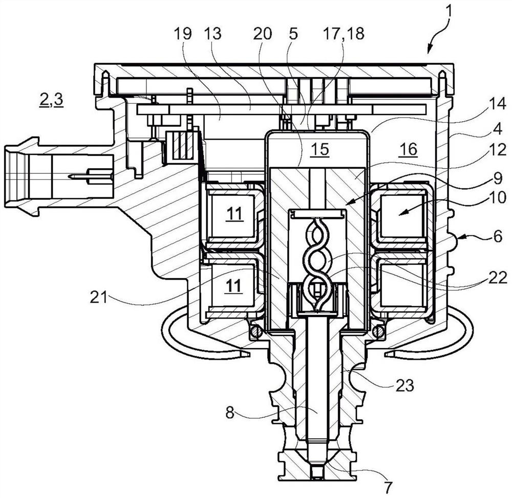
[0021] according to figure 1 , an expansion valve 1 according to the invention for an air conditioning unit 2 , a battery cooler and / or an oil cooler of a motor vehicle 3 has a housing 4 in which a sensor 5 (eg a 3D Hall sensor) is arranged and Stepper Motor 6 or BLDC Motor. A valve seat 7 and a valve body 8 interacting therewith are also provided. The stepper motor 6 or BLDC motor has a rotor 9 and a stator 10 surrounding the rotor 9, for example in figure 1 In the case shown, the stator has two coils 11 . The rotor 9 has permanent magnets 12 , wherein the sensor 5 is arranged on the control board 13 .

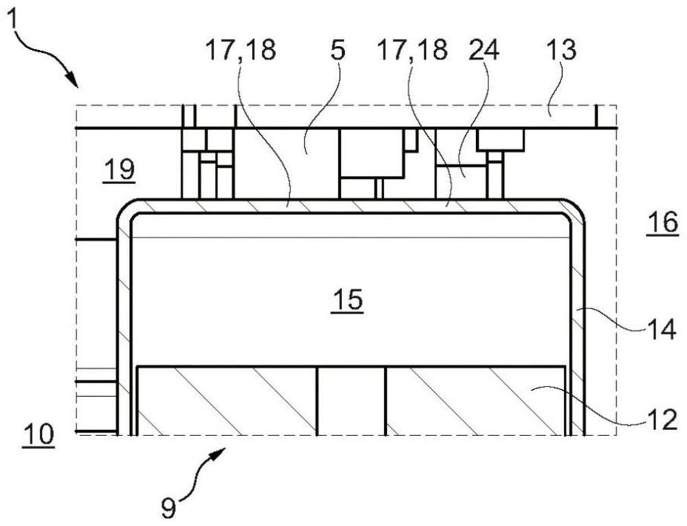
[0022] Furthermore, a separation tank 14 is provided, which surrounds the rotor 9 and separates the rotor-side wet area 15 from the stator-side dry area 16 . By means of the separation tank 14 the sensor 5 can be arranged in the dry area 16 and thus in a protected manner. According to the invention, the sensor 5 is now connected to the separation tank 14 via an adhesive ...


PUM


Abstract

The invention relates to an expansion valve (1): having a housing (4), a sensor (5), a stepping motor (6) or BLDC motor, a valve seat (7) and a valve body (8) interacting with the valve seat; -wherein the stepping motor (6) or BLDC motor has a rotor (9) and a stator (10) surrounding the rotor (9); the rotor (9) has permanent magnets (12) which are non-rotatably connected thereto; -wherein a separating tank (14) is provided, which surrounds the rotor (9) and separates a wet region (15) on the rotor side from a dry region (16) on the stator side; -wherein the sensor (5) is connected to the separating tank (14) via an adhesive layer (18) formed as a thermally conductive layer (17). As a result, temperature-dependent thermal expansion of the separating tank (14) can be eliminated, and a particularly precise detection of the position of the valve body (8) can be made possible.

Description

technical field [0001] The present invention relates to an expansion valve for an air conditioning system of a motor vehicle. Furthermore, the invention relates to an air conditioning system for a motor vehicle having such an expansion valve. Background technique [0002] An electrically actuatable valve is known from EP 3 392 538 A1, which valve has a rotor and a stator which is separated from the rotor via a separation tank. A sensor is provided to detect the rotational angular position of the rotor. [0003] An expansion valve (also known as a throttle valve) is a valve that increases or expands volume by reducing the pressure of the fluid flowing through it by locally constricting the flow cross-section. In air conditioning systems, especially in motor vehicles, such expansion valves reduce the pressure of the refrigerant that normally enters the expansion valve as a nearly boiling liquid. In doing so, an isenthalpic change of state occurs as the refrigerant expands a...

Claims


Application Information

Patent Timeline
Patent Type & Authority Applications(China)
IPC IPC(8): F16K31/06F16K37/00F25B41/345
CPCF16K31/0675F16K37/0041F16K37/005F25B41/345F25B41/35F25B49/02F25B2600/2513B60H1/00978B60H1/3225F25B49/005F25B41/31
Inventor 史蒂芬·胡布纳马蒂亚斯·林登贝格杰弗里·万德尔登弗洛里安·韦策尔
Owner MAHLE INT GMBH
Learn More