Strength controllable device and method for causing traumatic cerebral injury of insects

A traumatic, brain-injured technology, applied in animal husbandry and other directions, can solve the problems of uncontrollable impact force of experimental animals, influence of experimental analysis, randomness and other problems, achieve stable and controllable movement trajectory, achieve falling height, and easy production and preparation Effect

Active Publication Date: 2019-03-19
INST OF GENETICS & DEVELOPMENTAL BIOLOGY CHINESE ACAD OF SCI
View PDF2 Cites 3 Cited by
  • Summary
  • Abstract
  • Description
  • Claims
  • Application Information

AI Technical Summary

Problems solved by technology

[0004] The above two devices that cause brain damage in fruit flies mainly have the following problems: first, the impact force on experimental animals is uncontrollable and random; second, the impact parts on experimental animals are uncontrollable and random; third, In addition to head impact, it will also cause impact and damage to other parts, which will have a great impact on later experimental analysis

Method used


Image

  • Strength controllable device and method for causing traumatic cerebral injury of insects
  • Strength controllable device and method for causing traumatic cerebral injury of insects
  • Strength controllable device and method for causing traumatic cerebral injury of insects

Examples


Embodiment 1

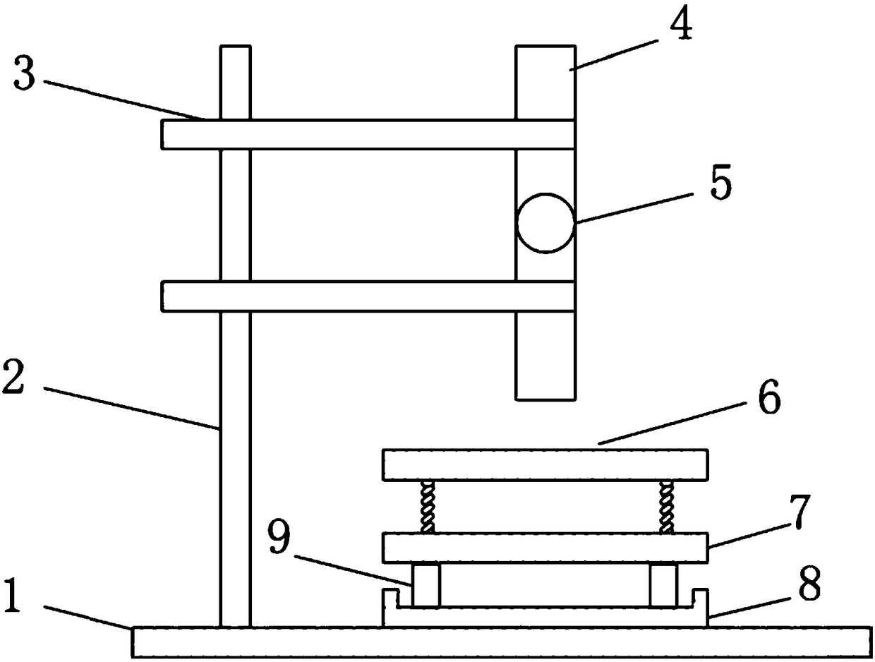
[0051] The experimental device causing insect traumatic brain injury of the present embodiment, such as figure 1 As shown, it includes a base 1 , a pole 2 , a clip 3 , a drop guide 4 , a steel ball 5 , an impact plate 6 , an insect fixing plate 7 , an insect collection container 8 and a spacer 9 . The base 1 is placed on the experimental table, the vertical pole 2 is fixed vertically on the base 1, the clamp 3 is horizontally fixed on the vertical pole 2, the drop guide 4 is fixed on the clamp 3, the impact plate 6 is placed above the base 1, and is in the falling position. Directly below the conduit 4, the central position of the falling conduit 4 should be aligned with the central position of the impact plate 6, the insect fixed plate 7 is located directly below the impact plate 6, and the insect collection container 8 is located directly below the insect fixed plate 7.

[0052] The base 1 is in the shape of a rectangle, a square or a disc, and is placed on the experimental ...

Embodiment 2

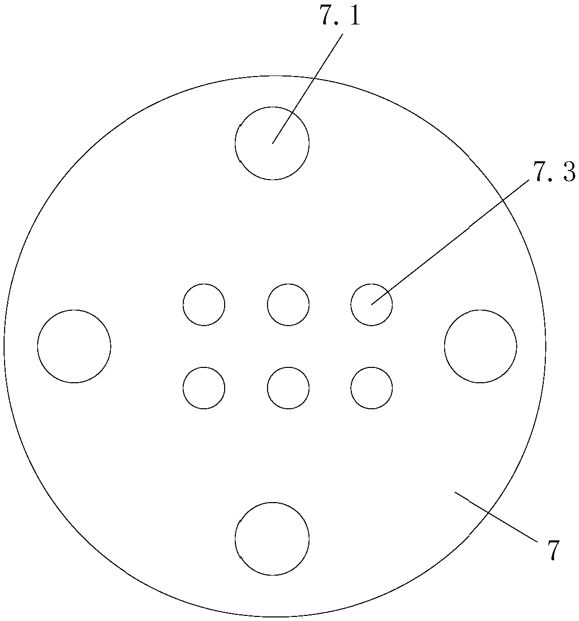
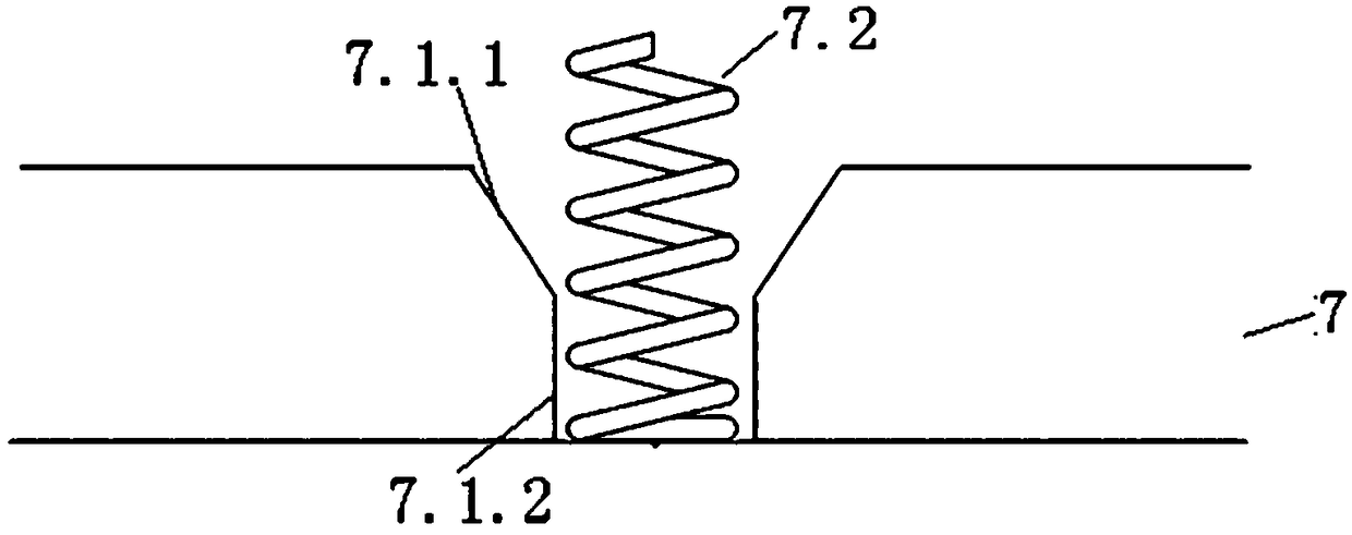
[0068] Such as Figure 4 As shown, the spring installation hole 7.1 includes a tapered hole 7.1.1 and a cylindrical hole 7.1.2. The spring installation hole 7.1 does not pass through the insect fixing plate 7, but is a groove structure. This structure allows the support spring 7.2 to be directly fixed in the spring installation hole 7.1 without the support of the washer 9 . Other structures of this embodiment are the same as those of Embodiment 2, and will not be repeated here.

Embodiment 3

[0070] Such as Figure 6 As shown, the axis of the tapered aperture 7.3 forms an acute angle with the insect fixed plate 7, and the side of the insect head is exposed on the surface of the insect fixed plate 7, and the side of the insect head is damaged by the impact force transmitted from the impact plate 6. Other structures of this embodiment are the same as those of Embodiment 1, and will not be repeated here.


PUM


Abstract

Provided are a strength controllable device and method for causing traumatic cerebral injury of insects. The device comprises a base, a vertical rod, a fixing part, a guide tube, a heavy object, a bumping plate and an insect fixing plate, wherein the vertical rod is vertically arranged on the base, the fixing part is horizontally arranged on the vertical rod and used for fixing the guide tube, thebumping plate is located under the guide tube, and the heavy object is placed in the guide tube and bumps against the bumping plate during falling when the device is used. The insect fixing plate islocated under the bumping plate and is provided with one or more insect fixing holes and multiple spring installing holes, supporting springs are arranged in the spring installing holes, the tops of the supporting springs are higher than the insect fixing plate, and the bumping plate is arranged on the supporting springs. The device is simple in structure, low in price and easy to produce and manufacture, and accurate control of insect head bumping strength and bumping part is achieved.

Description

technical field [0001] The invention relates to the field of biological experiment devices, in particular to a device and method for causing insect traumatic brain injury with controllable force. Background technique [0002] Traumatic brain injury (TBI) is an important global disease that threatens human brain health. According to statistics, the global average incidence rate of TBI is 2‰ (200 / 100,000), and the average death rate is 0.2‰ (20 / 100,000). / 100,000 (Reilly and Bullock, Current evaluation of TBI epidemiology in an aging society with improved preventative measures. Traumatic brain and spinal cord injury: challenges and developments, Cambridge University Press, Cambridge, 2005). Severe brain injury can lead to death of the patient, while mild brain injury can cause cognitive, mental and behavioral impairment of the patient (Zaloshnja et al., Prevalence of long-term disability from traumatic braininjury in the civilian population of the United States. The Journal ...

Claims


Application Information

Patent Timeline
Patent Type & Authority Applications(China)
IPC IPC(8): A01K67/033
CPCA01K67/033
Inventor 石文文张永清
Owner INST OF GENETICS & DEVELOPMENTAL BIOLOGY CHINESE ACAD OF SCI
Why Eureka
Try Eureka