Anti-collision structure for tail of freight car

A truck and anti-collision technology, which is applied to vehicle components, vehicle safety arrangements, bumpers, etc., can solve the problems of loading efficiency and convenience of maintenance, high strength and rigidity of the anti-collision beam, and cars rushing into the bottom of the truck, etc. , to achieve good cushioning energy absorption effect, high efficiency energy absorption, and avoid harm

Inactive Publication Date: 2019-03-19
HUAQIAO UNIVERSITY
View PDF9 Cites 4 Cited by
  • Summary
  • Abstract
  • Description
  • Claims
  • Application Information

AI Technical Summary

Problems solved by technology

Due to the high chassis of the truck, the high rigidity and strength of the box, and the low speed of the car, when the car rear-ends the truck, it is very easy to cause the car to rush into the bottom of the truck, so that the fragile car body and the truck compartment are directly connected. Therefore, trucks need to be equipped with rear anti-collision beams to prevent rear-end collisions from causing major injuries to the occupants of the rear vehicles
However, the strength and rigidity of the rear anti-collision beams of existing trucks are very large, and there is almost no deformation in the event of a rear-end collision, and the energy absorption is almost entirely borne by the rear vehicle anti-collision beams.
When an accident occurs, especially when the car is at high speed, it is difficult for the existing anti-collision beam to effectively absorb the impact energy caused by the collision, causing the longitudinal beam and the passenger compartment to bear a large amount of impact energy, which poses a threat to the safety of the occupants
At the same time, due to the existence of the rear anti-collision beam, the efficiency of truck loading and the convenience of maintenance have been greatly affected

Method used


Image

  • Anti-collision structure for tail of freight car
  • Anti-collision structure for tail of freight car
  • Anti-collision structure for tail of freight car

Examples


Embodiment Construction

[0024] The present invention will be further described below in conjunction with the accompanying drawings and specific embodiments.

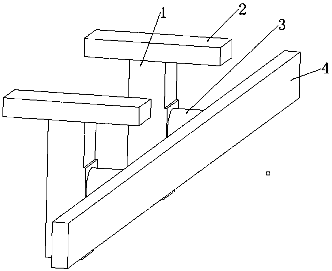
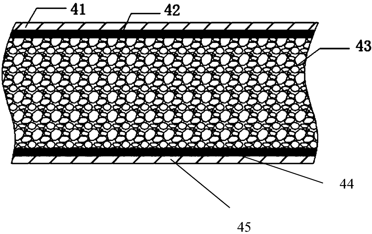
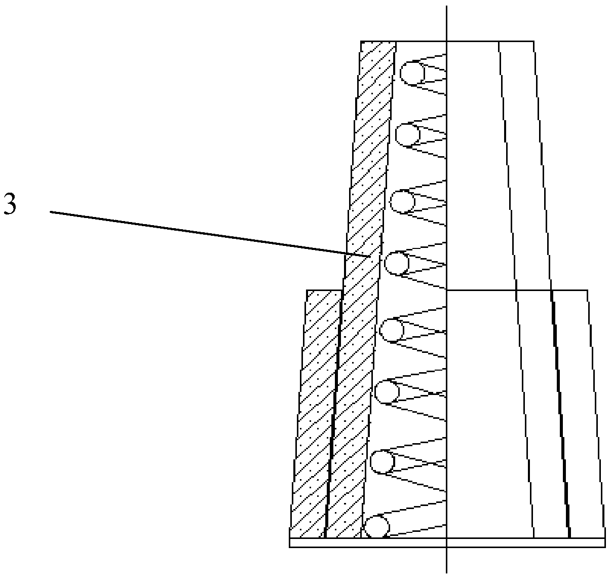
[0025] An anti-collision structure at the rear of a truck, comprising a vehicle longitudinal beam 2, a channel steel 1, an energy-absorbing box 3, and an anti-collision beam 4; the upper end of the channel steel 1 is connected to the vehicle longitudinal beam 2; the anti-collision beam 4 The length is set along the width direction of the car, and the energy-absorbing box 3 is connected to the side of the anti-collision beam 4; the side of the channel-shaped steel 1 close to the energy-absorbing box 3 is provided with a connector, and the energy-absorbing box 3 is connected to a An energy-absorbing box connector 5, which is detachably connected to the energy-absorbing box connector 5; the anti-collision beam 4 is sequentially composed of a first aluminum alloy plate 41, a first carbon fiber composite material 42, and foamed aluminum along its thi...


PUM


Abstract

The invention provides an anti-collision structure for the tail of a freight car. The structure comprises a car girder, channel steel, an energy absorption box and an anti-collision cross beam. The upper end of the channel steel is connected with the car girder. The length of the anti-collision cross beam is arranged in the width direction of the car, and the energy absorption box is connected with the side face of the anti-collision cross beam. A connecting part is arranged on the face, close to the energy absorption box, of the channel steel, the energy absorption box is connected with an energy absorption box connecting part, and the connecting part is detachably connected with the energy absorption box connecting part. The anti-collision cross beam is sequentially composed of a first aluminum alloy plate, a first carbon fiber composite, foamed aluminum, a second carbon fiber composite 44 and a second aluminum alloy plate in the thickness direction of the anti-collision cross beam.By means of the technical scheme, the buffer energy absorption performance and rapid and convenient dismounting and mounting of the anti-collision cross beam can be achieved.

Description

technical field [0001] The invention relates to the technical field of automobile safety equipment, in particular to an anti-collision structure at the rear of a truck. Background technique [0002] With the development of the economy and the increase of freight volume, truck transportation has increasingly become an irreplaceable mode of transportation. The relevant safety performance of trucks has become an important issue that people cannot ignore. The rear anti-collision beam of a truck is an important device used to ensure the safety of the rear vehicle personnel. Due to the high chassis of the truck, the high rigidity and strength of the box, and the low speed of the car, when the car rear-ends the truck, it is very easy to cause the car to rush into the bottom of the truck, so that the fragile car body and the truck compartment are directly connected. Collision can easily cause injury to the occupants of the car. Therefore, the truck needs to be equipped with a rear...

Claims


Application Information

Patent Timeline
IPC IPC(8): B60R19/22B60R19/56
CPCB60R19/22B60R19/56
Inventor 张勇陈慧超侯玉波陆勇何宁
Owner HUAQIAO UNIVERSITY
Why Eureka
Try Eureka