
Aircraft composite material wing spar and wing butt zone connection structure

A technology for connecting structures and composite materials, applied in the aviation field, can solve the problems of unfavorable composite spar design, difficult spar fastener arrangement, and high proportion of transmitted loads, so as to avoid the risk of stress concentration, reduce the number, and reduce the The effect of assembly difficulty

Active Publication Date: 2019-03-19
BEIJING AERONAUTIC SCI & TECH RES INST OF COMAC +1
View PDF4 Cites 14 Cited by
  • Summary
  • Abstract
  • Description
  • Claims
  • Application Information

AI Technical Summary

Problems solved by technology

Depending on the specific details of the structure, strip plates, cross joints, or three-prong joints may be used at the connection surface; there are many fasteners in the wing root connection area and the specifications are large, and the weight reduction design of the wing spar and the arrangement of fasteners are difficult. Larger; the rigidity design of the connection area between the wing spar and the wing wall, the central wing spar and the root rib web is relatively large, and the corresponding transfer load ratio is too high, which is not conducive to the design of the composite spar

Method used


Image

  • Aircraft composite material wing spar and wing butt zone connection structure
  • Aircraft composite material wing spar and wing butt zone connection structure
  • Aircraft composite material wing spar and wing butt zone connection structure

Examples


Embodiment Construction

[0022] In order to make the object, technical solution and advantages of the present invention clearer, the present invention will be further described in detail below in conjunction with the accompanying drawings and embodiments. It should be understood that the specific embodiments described here are only used to explain the present invention, not to limit the present invention. On the contrary, the invention covers any alternatives, modifications, equivalent methods and schemes within the spirit and scope of the invention as defined by the claims. Further, in order to make the public have a better understanding of the present invention, some specific details are described in detail in the detailed description of the present invention below. The present invention can be fully understood by those skilled in the art without the description of these detailed parts.

[0023] The present invention will be further described below in conjunction with the accompanying drawings and ...


PUM


Abstract

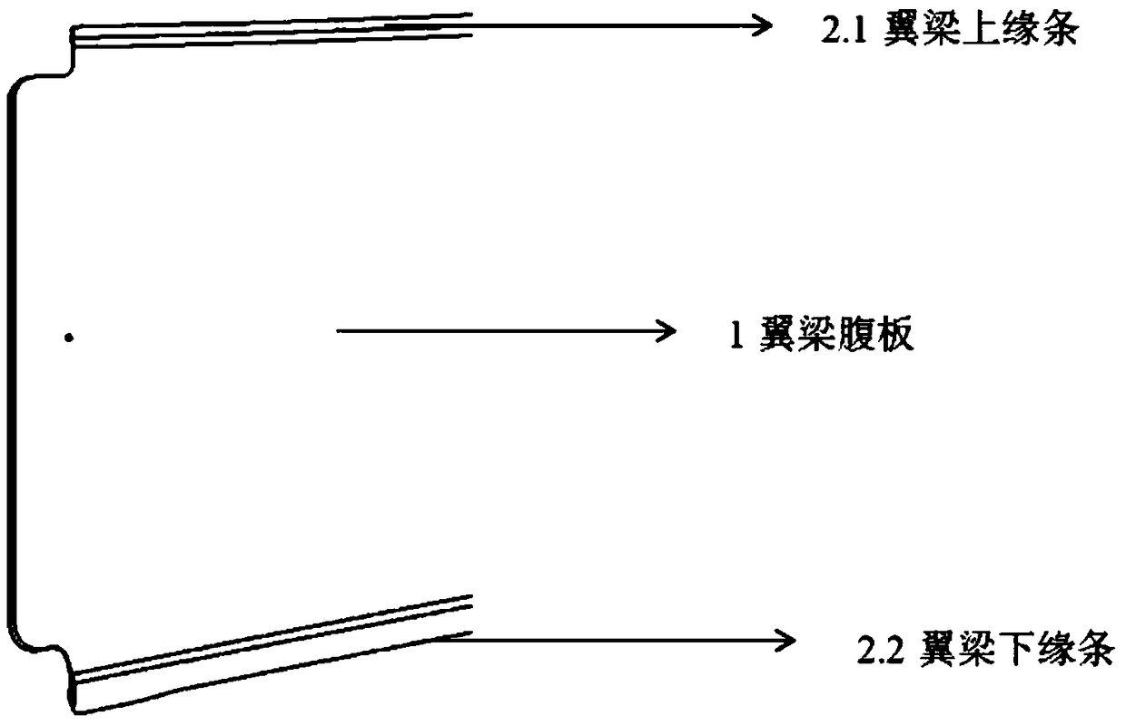
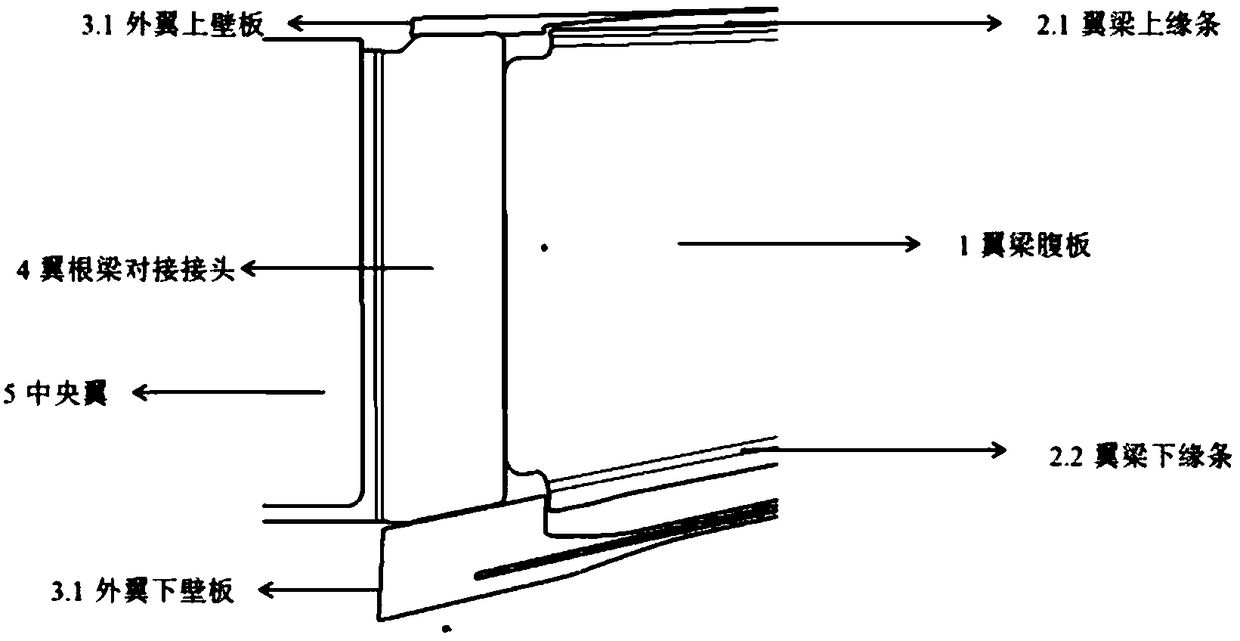
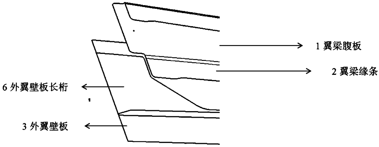
The invention provides an aircraft composite material wing spar and wing butt zone connection structure. In the structure, a wing spar has a C-type configuration, and is formed by a spar web, a spar upper flange and a spar lower flange; the composite material wing spar is prepared by adopting processes of manual pasting, automatic tape-laying with thermal diaphragm forming, automatic fiber-placement and the like; the wing spar is connected with an outer wing wall plate and a connection joint by adopting fastening parts; and the wing spar is arranged at the joint of a wing butt, is stopped in advance according to the butt joint requirement, is not directly butted with a wing butt, a wing rib or center wing spar, can be used for cutting an end socket to avoid stress concentration caused in avariable cross-section zone when load is transferred, and can perform fillet treatment on an edge zone.

Description

technical field [0001] The invention belongs to the field of aviation technology, in particular to an aircraft composite material wing spar and wing root area connecting structure. Background technique [0002] With the development of technology, more and more composite materials are used in aircraft structures, which can effectively reduce the weight of aircraft, prolong the fatigue life of structures, and extend the time interval for normal maintenance of aircraft. There are generally two forms of wing spar connection structure: one is the butt joint structure; the other is the lap joint structure. At present, the connection form of existing wings is more reflected in the connection of metal spars. Most of the connection forms between the spars are butt joint structures, and the butt joints of the beams are designed to overlap the spars. [0003] After the aircraft wing adopts a composite material structure, due to the properties of the composite material itself, the open...

Claims


Application Information

Patent Timeline
IPC IPC(8): B64C3/18
CPCB64C3/18B64C3/182
Inventor 谢汶轩沈裕峰高举斌张发肖志鹏梁斌季少华王栋刘传军
Owner BEIJING AERONAUTIC SCI & TECH RES INST OF COMAC
Learn More