
Battery replacing system

An electric system and battery technology, applied in the direction of electric power devices, circuits or fluid pipelines, lifting devices, etc., to achieve the effects of reducing friction area, stable lifting, and labor-saving driving

Pending Publication Date: 2019-03-19
GUANGZHOU XUANTONG JIENENG TECH CO LTD
View PDF7 Cites 2 Cited by
  • Summary
  • Abstract
  • Description
  • Claims
  • Application Information

AI Technical Summary

Problems solved by technology

[0003] The object of the present invention is to provide a battery replacement system in order to solve the above-mentioned technical problems existing in the existing large-scale electric drive equipment

Method used


Image

  • Battery replacing system
  • Battery replacing system
  • Battery replacing system

Examples


Embodiment 1

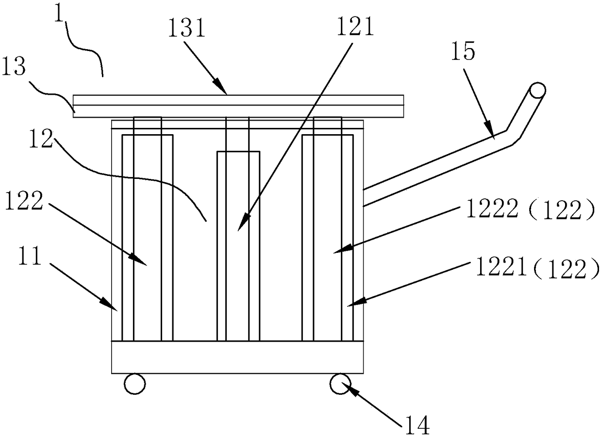
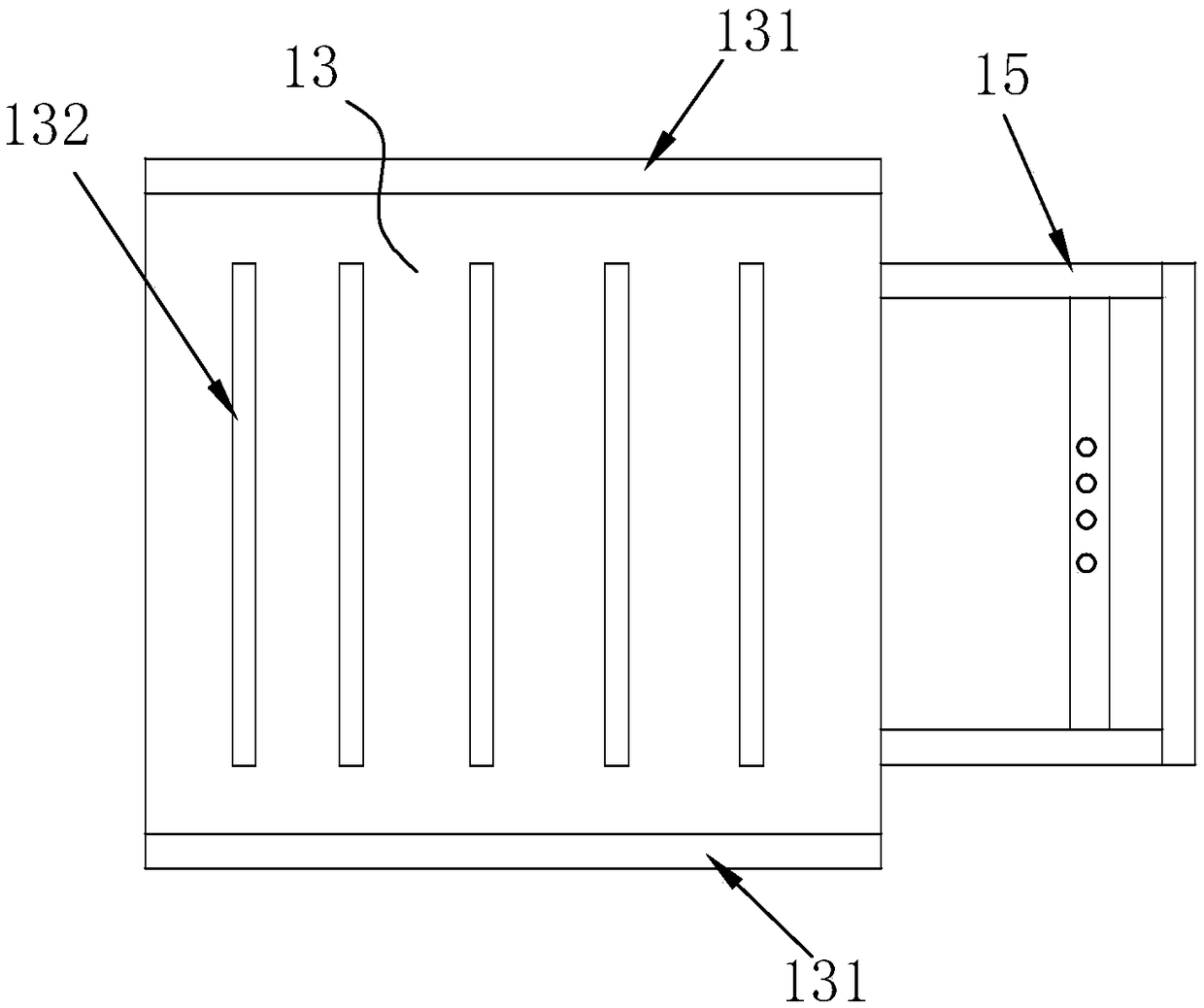
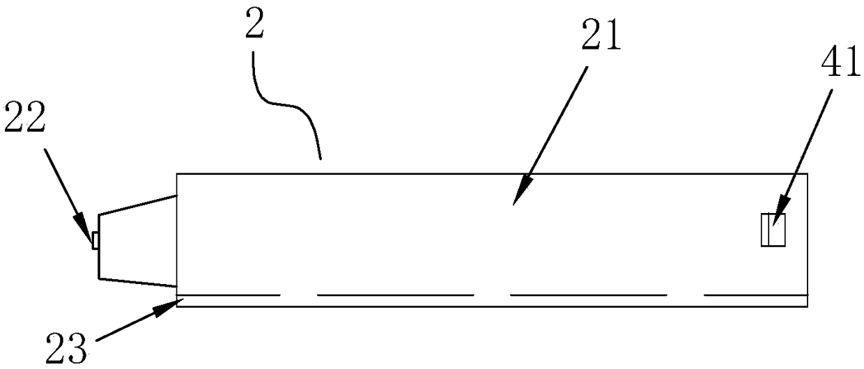
[0035] refer to Figure 1 to Figure 7 The power exchange system shown includes a push car 1, a storage battery 2 and a battery compartment 3. The push car 1 is composed of a car body 11, a lifting mechanism 12 and a lifting platform 13. The lifting mechanism 12 is provided with a car body 11, the lifting platform 13 is a lifting platform installed on the lifting mechanism 12, the lifting platform 13 is located above the vehicle body 11, and forms an up and down lifting structure on the vehicle body 11 through the lifting mechanism 12; the storage battery 2 includes There is a battery main body 21 and a male plug 22, the battery main body 21 is a square body, and the male plug 22 is arranged on the outside of the battery main body 21, such as being arranged on the front side of the battery main body 21; the battery compartment 3 is for installation In the open inner cavity on the electric device 8, the shape and size of the battery compartment 3 correspond to the storage batter...

Embodiment 2

[0043] refer to Figure 8 with Figure 9 As shown, the technical characteristics of this embodiment are: the opening of the battery compartment 3 is provided with a safety door 6, and the inner side of the safety door 6 is provided with an elastic pressing block 7, which is made of soft rubber. into briquettes. In specific applications, the storage battery 2 is pressed tightly in the battery compartment 3 by the elastic pressing block 7, which effectively prevents the storage battery 2 from loosening in the battery compartment 3 or detaching from the battery compartment 3, making the use more stable, safe and reliable, and the rest are the same as above Example.

[0044] When the present invention is applied, the electric equipment 8 includes electric aircraft and electric vehicles. Such as Figure 10 As shown, when the battery is replaced on an electric aircraft, the storage battery 2 is picked up by the push car 1 and transported to the corresponding position of the batt...


PUM


Abstract

The invention relates to a battery replacing system. The battery replacing system comprises a trolley, a storage battery and a battery bin. The trolley is composed of a trolley body, a lifting mechanism and a lifting platform. The lifting mechanism is arranged in the trolley body. The lifting platform is mounted on the lifting mechanism. The lifting platform is located above the trolley body. An up-down lifting structure is formed on the trolley body through the lifting mechanism. The storage battery comprises a battery body and a power male connector. The battery body is a cuboid. The power male connector is arranged on the outer side of the battery body. The battery bin is an open inner cavity mounted on electric equipment. The battery bin corresponds to the storage battery in shape andsize. The inner wall of the battery bin is provided with a power female connector corresponding to the power male connector on the storage battery. During application, the battery replacing system hasthe advantages that the battery is easy and convenient to replace, operation is easy, time and labor are saved, and thus, the battery replacing system is more beneficial to application and popularization of large-scale electric equipment such as electric cars and electric airplanes.

Description

technical field [0001] The invention relates to a battery replacement device, in particular to a replacement system for large battery packs of electric vehicles, electric airplanes and other electric equipment. Background technique [0002] In large-scale electric drive equipment such as automobiles and airplanes, due to the limitations of existing storage battery technology, in order to ensure the continuity of driving such as automobiles and airplanes, the storage batteries produced are large in size and medium in quality, resulting in difficulty in replacement and high maintenance costs , so as to hinder the development of electric vehicles, aircraft and other large equipment. Contents of the invention [0003] The object of the present invention is to provide a power exchange system in order to solve the above-mentioned technical problems existing in the existing large-scale electric drive equipment. [0004] The object of the invention can be realized through the fol...

Claims


Application Information

Patent Timeline
Patent Type & Authority Applications(China)
IPC IPC(8): B66F7/06B60S5/06
CPCB66F7/0625B60S5/06
Inventor 成志雄
Owner GUANGZHOU XUANTONG JIENENG TECH CO LTD
Learn More