Battery charging mechanism

A battery charging and battery technology, applied in battery circuit devices, electric vehicle charging technology, charging stations, etc., can solve the problems of high labor costs, potential safety hazards, and low efficiency, and achieve smart structure, simple battery replacement, and improved The effect of power exchange efficiency

Active Publication Date: 2021-02-02
ZHEJIANG GEELY HOLDING (GROUP) CO LTD +1
View PDF3 Cites 0 Cited by
  • Summary
  • Abstract
  • Description
  • Claims
  • Application Information

AI Technical Summary

Problems solved by technology

[0003] In the existing battery replacement methods currently on the market, the removed batteries are sent to the charging bank or charging compartment for charging and maintenance, and the battery is pushed to dock with the charging port by manual or power-assisted arms. This method has high labor costs, low efficiency, and There are potential safety hazards, which limit the realization of fully automated electric vehicle quick battery replacement without manual intervention

Method used


Image

  • Battery charging mechanism
  • Battery charging mechanism
  • Battery charging mechanism

Examples


Embodiment 1

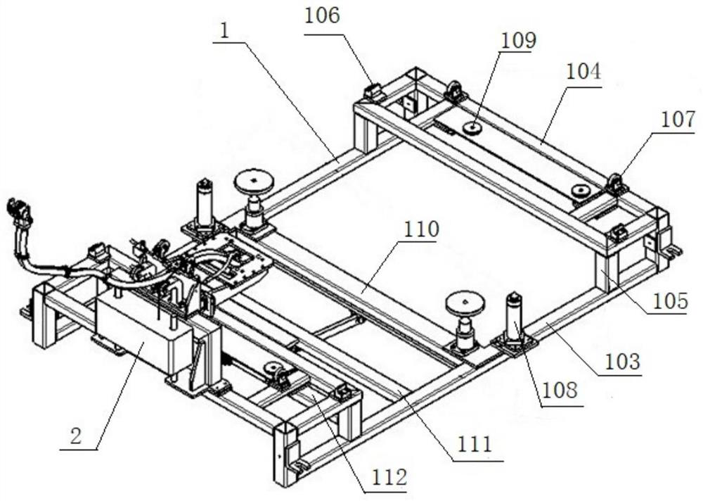
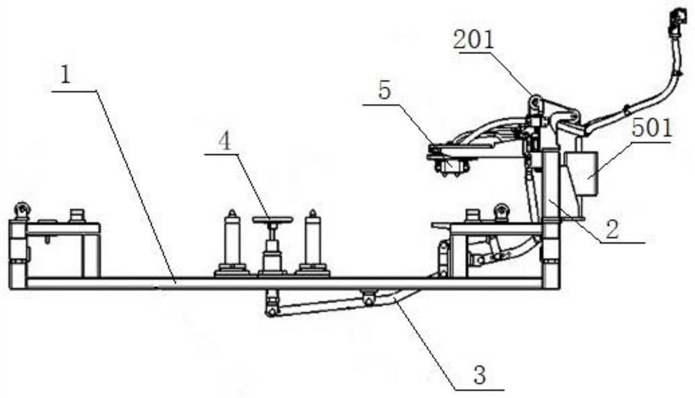
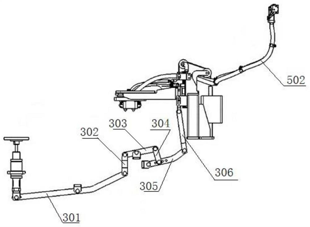
[0033] Such as Figure 1-5 As shown, the present invention provides a battery charging mechanism, comprising:

[0034] The support frame 1 is provided with guide rails and limiting parts for placing batteries, such as figure 1 As shown, in this embodiment, the support frame 1 also includes a bottom frame 103 and two upper frames 104; wherein, the bottom frame 103 includes two horizontal bars arranged in parallel, and a second horizontal bar vertically connected to the two horizontal bars is also provided. A fixed rod 110 and the third fixed rod 112; an upper frame 104 is fixed on one end of the bottom frame 103 by a column 105, and another upper frame 104 is fixed on the other end of the bottom frame 103 by a column 105, and the two upper frames 104 form The horizontal support surface is the place where the battery is finally charged. It should be noted that the figure shows that the number of columns 105 is eight, that is, each of the four corners of the upper frame 104 is p...

Embodiment 2

[0049] Such as Figure 6-8 As shown, the battery charging mechanism provided by the present invention is applied in the battery charging bank, and realizes the automation of the whole process of electric vehicle battery replacement.

[0050] The above-mentioned battery charging warehouse includes a container 10 as a warehouse body, a stacking trolley 7, a telescopic fork 8, several battery charging mechanisms and a plurality of shelves 6 for placing the battery charging mechanisms.

[0051] Four battery charging mechanisms are successively stacked on each shelf 6, and each battery charging mechanism is detachably fixed on the shelf 6 through a connector. Three shelves 6 form a large charging matrix, and each charging unit corresponds to a For the battery charging mechanism, one side wall of the container 10 is set as the door of the charging warehouse, and a stacking trolley 7 is arranged on the side of the charging matrix close to the warehouse door, and the stacking trolley ...


PUM


Abstract

The invention provides a battery charging mechanism, which comprises a support frame provided with a guide rail and a limiting part, wherein the supporting frame is used for placing a battery; a charging table arranged at one end of the supporting frame; and a U-shaped connecting rod, wherein a rotating shaft of the U-shaped connecting rod is arranged on the supporting frame, and the two ends of the U-shaped connecting rod are both located on one side of the charging table, one end of the U-shaped connecting rod is connected with a tray, the tray is used for being in contact with the bottom surface of a battery and driving the U-shaped connecting rod to rotate when bearing the pressure of a battery, and an electric connector is arranged at the other end of the U-shaped connecting rod and used for making contact with a charging terminal of a battery when the U-shaped connecting rod rotates. According to the battery charging mechanism, automatic butt joint charging of the battery can beachieved, the labor cost is saved, and the battery replacing efficiency is improved.

Description

technical field [0001] The invention relates to the technical field of electric vehicles, in particular to a battery charging mechanism capable of automatic docking after the battery of the electric vehicle is placed. Background technique [0002] Electric vehicles use electricity as energy and are green vehicles. There are generally two ways to supplement electric energy for electric vehicles. One is to charge the whole vehicle. The fast charge can reach 30 minutes. The other is the battery replacement method, which takes about 10 to 20 minutes depending on the degree of automation of the replacement equipment. The replaced battery is maintained by a special facility, and the slow charging method is used to prolong the life. In order for electric vehicles to be able to run continuously and shorten the waiting time for power replenishment, it is an ideal operation method to use battery replacement, that is, remove the battery that needs to be charged from the vehicle, repla...

Claims


Application Information

Patent Timeline
Patent Type & Authority Applications(China)
IPC IPC(8): H02J7/00B60L53/80
CPCH02J7/0045B60L53/80Y02T90/14
Inventor 何星明吴元和邬波
Owner ZHEJIANG GEELY HOLDING (GROUP) CO LTD
Why Eureka
Try Eureka