Supercharge Your Innovation With Domain-Expert AI Agents!

Trash rack and rack cleaning clamp

A technology for trash racks and fences, which is applied in the field of trash racks and fence cleaning clips. It can solve the problems of easy hanging on the tip of the tooth, hard to see and reach, and difficult to clean. It is easy to clean, not easy to fall off, and clamps strong effect

Inactive Publication Date: 2019-03-19
陈爱军
View PDF6 Cites 1 Cited by
  • Summary
  • Abstract
  • Description
  • Claims
  • Application Information

AI Technical Summary

Problems solved by technology

[0003] Fence-style trash racks and grid trash racks are commonly used at present. After they intercept a large amount of discarded clothes, plastic convenience bags, plastic woven bags, silk strips, and soft sheet floating objects, these floating objects will Adhesive to the fence, because the current cleaning clips are pinch-type clips, easy to fall off, with clips that prevent teeth from falling off, the object to be cleaned is easy to hang on the tip of the teeth, and it is not easy to fall after adding up, especially the fence The lower grille goes deep into the water, so it is hard to see and reach, and it is very difficult to clean

Method used


Image

  • Trash rack and rack cleaning clamp
  • Trash rack and rack cleaning clamp
  • Trash rack and rack cleaning clamp

Examples


Embodiment 1

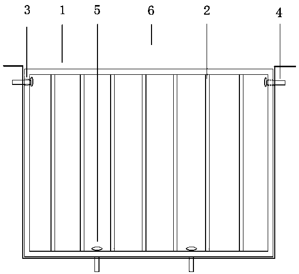
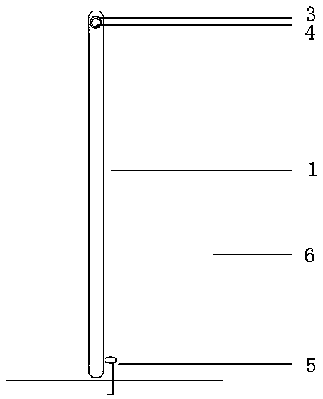
[0024] Embodiment 1; as figure 1 and 2 As shown, there is a fence frame (1) on the trash control fence, and more than one grid bar (2) is arranged on the fence frame (1), and there is a fence frame (1) on the opposite sides of the upper part of the fence frame (1). Through holes (3), each through hole (3) has a fixing bolt (4), the through hole (3) is flexibly connected with the fixing bolt (4), and the height and length of the fence frame (1) are smaller than the water tank (6 ), the height and length of the cross-section, the fixing bolts (4) fix the trash rack on the upper part of both sides of the water tank (6), place it on the bottom of the water tank (6), make the fence frame (1) vertical, and the fence frame (1 ) at least one stop bolt (5) is fixedly installed on one side of the water flow direction, and the height of the stop bolt (5) is higher than the height of the lower part of the fence frame (1).

[0025] When cleaning, the fixed bolt (4) becomes the rotating s...

Embodiment 2

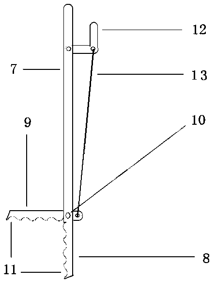
[0026] Embodiment 2; as image 3 and 4 As shown, the fence cleaning clip includes the cleaning clip handle (7), the fixed clip (8) and the movable clip (9) are located under the cleaning clip, and there are corrugated teeth on the jaws of the movable clip (9) and the fixed clip (8) ( 11), the cross-section of the fixed clip (8) is in the shape of a U-shaped groove, when the cleaning clip is closed, the corrugated teeth of the movable clip (9) fit into the U-shaped groove of the fixed clip (8), just like the fixed clip (8) ) Hold the movable clip (9), the rotating shaft (10) passes through the shaft holes of the movable clip (9) and the fixed clip (8), the movable clip (9) and the fixed clip (8) are connected through the rotating shaft (10), fixed There is an opening at the cross position of the U-shaped groove shaft hole of the clamp (8), and the movable clamp (9) passes through the opening of the U-shaped groove of the fixed clamp (8) to expose the clamp handle, and the pull...


PUM


Abstract

The invention provides a trash rack and a rack cleaning clamp. Through holes in the two sides of the upper portion of a rack frame are movably connected with fixing bolts, a retaining bolt is fixedlymounted on one side of the water flow direction of the rack frame, during cleaning, the fixing bolts serve as rotary shafts, the rack frame below the trash rack is hooked through a hook, the trash rack is put flat, the trash rack is separated from the water surface, and therefore the trash rack is very easy to clean. The rack cleaning clamp is changed into a U-shaped groove holding type from a common cleaning clamp pinching type, clamping is firm, disengagement is not likely to occur, corrugated teeth are used for a clamp opening of the rack cleaning clamp, and the defect of hooking of tooth tops of anti-disengaging teeth is avoided.

Description

technical field [0001] The invention relates to the fields of environmental protection and city appearance management, in particular to a trash fence and a fence cleaning clip. Background technique [0002] With the expansion of the scope of human activities, all kinds of industrial waste and domestic garbage are scattered everywhere. These garbage and the large amount of pollutants they contain will eventually be scattered and drifted to the receiving water body under the action of wind and rain. In addition, it will cause great pollution and serious harm to the ecological environment, so it is necessary to intercept floating objects in the water flow in the drainage ditches of residential areas, rivers and rivers, and the upstream of urban drainage systems. [0003] Fence-style trash racks and grid trash racks are commonly used at present. After they intercept a large amount of discarded clothes, plastic convenience bags, plastic woven bags, silk strips, and soft sheet flo...

Claims


Application Information

Patent Timeline
IPC IPC(8): E03F5/14E03F7/08
CPCE03F5/14E03F7/08
Inventor 陈爱军
Owner 陈爱军
Features
  • R&D
  • Intellectual Property
  • Life Sciences
  • Materials
  • Tech Scout
  • Unparalleled Data Quality
  • Higher Quality Content
  • 60% Fewer Hallucinations
Learn More