
Simulation calculation method for a double-face slit coating contact type die head

A slit coating and analog computing technology, applied in the direction of calculation, design optimization/simulation, special data processing applications, etc., can solve the problem of not considering the deformation of the substrate, and cannot guide the design of double-sided slit coating contact die , not applicable to the simulation of double-sided slit coating, etc., to achieve the effect of improving the accuracy and reliability of numerical prediction

Active Publication Date: 2019-03-19
SHENZHEN XINYUREN TECH
View PDF6 Cites 4 Cited by
  • Summary
  • Abstract
  • Description
  • Claims
  • Application Information

AI Technical Summary

Problems solved by technology

Another example is the literature (Liang Junjie, Zhou Huamin, Tao Bo, etc. Numerical simulation and analysis of the flow field of the double-cavity lithium battery coating slurry slot die [J]. Mold Industry, 2016, 42(10): 5-10 ., Zhou Yunfu. Research on slit coating head for power lithium battery pole piece [D]. Southeast University, 2014.) etc. used CFD method to simulate the cavity of double-cavity slit coating die used in single-sided slit slurry flow and die head design method, but the above-mentioned documents are only for the simulation of single-side coating process, without considering the deformation of the substrate when coating the second side in the double-sided slit coating process, and Not suitable for double-sided slot coating simulation and cannot guide double-sided slot coating contact die design

Method used


Image

  • Simulation calculation method for a double-face slit coating contact type die head
  • Simulation calculation method for a double-face slit coating contact type die head
  • Simulation calculation method for a double-face slit coating contact type die head

Examples


Embodiment

[0039] The specific implementation manners of the present invention will be described in detail below in conjunction with the accompanying drawings.

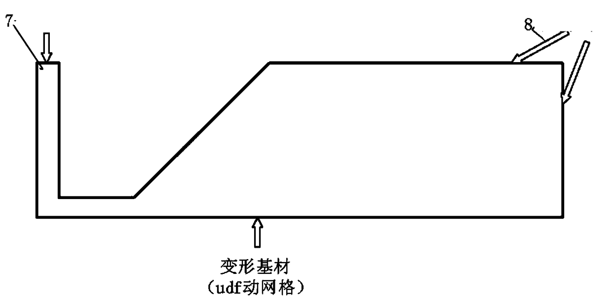
[0040] Step 1: Establish the geometric model of the calculation domain formed by the lip part of the double-sided slot coating contact die and the substrate, such as image 3 shown.

[0041] The base material is copper foil, and the main material properties are: density ρ=8900kg / m 3 , elastic modulus E=121GPa, thickness t=10μm. The flow field medium is lithium battery slurry and air, the slurry properties are: non-Newtonian fluid, density ρ=1340kg / m 3 ,, satisfy the power law model μ=kγ n =59.4*γ 0.37 , the surface tension is 0.05132N / m, and the contact angle with the substrate is 25.6°; the air properties are: density ρ=1.225kg / m 3 , Dynamic viscosity μ=1.7895e-5kg / (m·s).

[0042] Step 2: Grid division of flow field calculation domain.

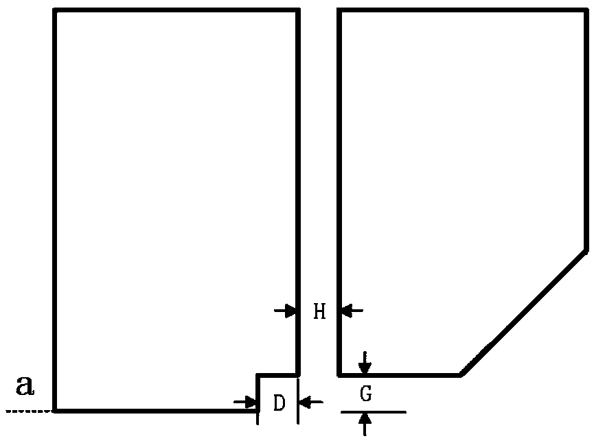
[0043] Mesh the flow field area, such as Figure 4 As shown, here G=0.25mm, H=0.4mm...


PUM


Abstract

The invention belongs to the related field of coating in the reel-to-reel manufacturing process, and discloses a simulation calculation method of a double-face slit coating contact type die head, which comprises the following steps of: (1) establishing a geometric model of a calculation domain formed by a die lip part of the double-face slit coating contact type die head and a base material; (2) flow field grid division; (3) establishing a VOF two-phase flow model and a base material deformation model of the slurry flow field; (4) giving a boundary condition and an initial condition for initialization, and performing initial flow field calculation; and (5) carrying out fluid-solid coupling numerical calculation by taking the steady flow field numerical calculation result (mainly the pressure distribution of the surface of the substrate) in the step (4) as an initial condition. On the basis of a VOF and fluid-solid coupling simulation method, the design of the double-sided slit coatingcontact type die head is guided through computational simulation, the manufacturing cost of the die head can be effectively reduced, and the coating uniformity is improved. According to the method, the influence of base material deformation on the coating liquid bead forming process and the coating uniformity due to lack of a back roller support in the second surface coating process in the double-surface coating process is fully considered, and the numerical prediction precision and reliability are improved by performing secondary development on FLUENT and embedding a user-defined program of the base material deformation.

Description

technical field [0001] The invention relates to the field of computer numerical simulation and coating in the roll-to-roll manufacturing process, and more specifically, relates to a simulation calculation method for a double-sided slit coating contact die head. Background technique [0002] Coating is the manufacturing process of uniformly coating the slurry prepared in the previous process on the substrate, drying it in an oven, and finally recycling it into rolls. It is an indispensable step in the roll-to-roll manufacturing process and also directly affects the product. The key process of capacity and consistency. At present, the mainstream coating technology mainly adopts single-sided slot coating, that is, coating the first side of the substrate first, drying and winding before unwinding, coating the second side of the substrate and then drying and winding. There are two main problems with this coating method. One is that the slurry coated on the first side will go thr...

Claims


Application Information

Patent Timeline
Patent Type & Authority Applications(China)
IPC IPC(8): G06F17/50
CPCG06F30/20
Inventor 杨志明周华民张云王云明周军
Owner SHENZHEN XINYUREN TECH
Learn More