Expressway tunnel fire rescue device

A technology for highways and tunnels, applied in the field of tunnel fire rescue, which can solve the problems of long distance between fire hydrants, rear-end collision, scratching, and hindering the progress of basic rescue.

Pending Publication Date: 2019-03-22
胡军
View PDF0 Cites 10 Cited by
  • Summary
  • Abstract
  • Description
  • Claims
  • Application Information

AI Technical Summary

Problems solved by technology

Highway tunnels are suitable for complex terrain, large transportation volume, high-efficiency and high-speed transportation requirements, but there are also great potential safety hazards in the tunnel. The closed structure of the tunnel is not conducive to rescue. Once a fire breaks out in the tunnel, accidents such as rear-end collisions and scratches are prone to occur. making the tunnel impossible to open to traffic
Many tunnels lack fire extinguishing water and fire extinguishers, fire hydrants are too far apart, and there are few rescue tools. Once a fire occurs, the on-site personnel cannot extinguish the fire in time.
[0003] Highway tunnels are located in areas away from the city center or in mountainous areas with complex terrain. When a fire breaks out in the tunnel, on the one hand, the high temperature and closed tunnel environment are not conducive to the diffusion of flammable gases. The cause of the fire, and the fact that it was difficult for the victims to escape, would inevitably cause heavy losses; in addition, the remote mountainous area and the complicated scene environment hindered the progress of the basic re

Method used


Image

  • Expressway tunnel fire rescue device
  • Expressway tunnel fire rescue device
  • Expressway tunnel fire rescue device

Examples


Embodiment Construction

[0037] The present invention will be described in further detail below in conjunction with the embodiments and with reference to the accompanying drawings.

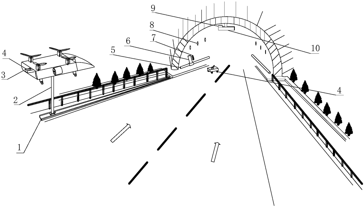
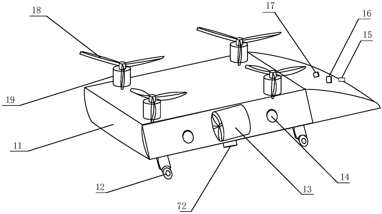
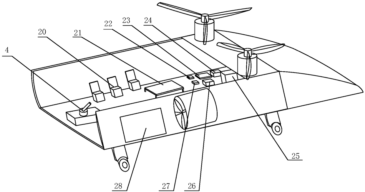
[0038] see Figures 1 to 11 , showing a fire rescue device for a highway tunnel in the present invention, including a guide rail 1, a power supply pole 2, a flying fire truck 3, a fire fighting trolley 4, a water pipe 5, a tee pipe 6, a water valve 7, and a fire detection device 8. Control system 9, display device 10.

[0039] Such as figure 1 As shown, a guide rail 1 is set between the expressway green belt and the overtaking lane, and the flying fire truck 3 flies along the guide rail 1, and keeps flying at a certain height with the green belt, and sends medical personnel, firefighters, and fire fighting vehicles 4 to the place where the emergency occurs. The location of the tunnel where the fire is located. Firefighters enter the tunnel to rescue the victims. The fire fighting vehicle 4 goes to the vicinity of the fi...


PUM


Abstract

The invention discloses an expressway tunnel fire rescue device. The expressway tunnel fire rescue device comprises a guide rail, a power supply rod, a flying fire fighting vehicle, a fire fighting trolley, a water pipe, a three-way pipe, a water valve, fire detection devices, a control system and a display device. The water pipe is installed in a tunnel to serve as a fire fighting water source ofthe tunnel. When the fire fighting trolley enters the tunnel where a fire happens, firefighters guide the water in the water pipe into the fire fighting trolley, and the fire fighting trolley moves forwards to find out the position of a fire source, rapidly pumps out the water in the water pipe and sprays the water to the fire source. The display device is adopted to remind drivers located outside the tunnel not to enter the tunnel where the fire happens, and therefore the phenomenon that the rear-end collision happens due to the fact that vehicles located outside the tunnel enter the tunnelblindly, or the unnecessary trouble is caused due to the fact that the vehicles run to the fire source is avoided. The flying fire fighting vehicle flies above a green belt, the medical personnel, thefirefighters and the fire fighting trolley are rapidly sent to the position where the fire happens, and therefore the victim rescue time is greatly saved.

Description

technical field [0001] The invention relates to the field of tunnel fire rescue, in particular to a fire rescue device for expressway tunnels. Background technique [0002] With the rapid development of highways, the proportion of tunnels is increasing. The construction of tunnels can make cars less detours, and there is no need to drive around mountains when crossing mountains and ridges. This greatly shortens driving time, reduces fuel consumption, and reduces vehicle exhaust emissions. emission. Highway tunnels are suitable for complex terrain, large transportation volume, high-efficiency and high-speed transportation requirements, but there are also great potential safety hazards in the tunnel. The closed structure of the tunnel is not conducive to rescue. Once a fire breaks out in the tunnel, accidents such as rear-end collisions and scratches are prone to occur. This makes the tunnel impossible to open to traffic normally. Many tunnels lack fire extinguishing water s...

Claims


Application Information

Patent Timeline
IPC IPC(8): A62C37/00A62C31/02A62C3/00B64D1/18B64C27/08
CPCA62C37/00A62C3/00A62C31/02B64C27/08B64D1/18
Inventor 胡军夏侯肖祥胡成韩亚琴
Owner 胡军
Why Eureka
Try Eureka