Pipe body end treatment equipment

A technology for pipe end and processing equipment, which is applied in metal processing equipment, feeding devices, positioning devices, etc., and can solve problems such as surface wrinkles of pipe fittings, affecting processing accuracy and quality, and wasting time

Pending Publication Date: 2019-03-22
HUNAN TENYUM INTELLIGENT EQUIP +1
View PDF0 Cites 5 Cited by
  • Summary
  • Abstract
  • Description
  • Claims
  • Application Information

AI Technical Summary

Problems solved by technology

[0003] The tube expansion process at the present stage mostly adopts a one-step operation method. When the expanded size range of the tube end is small, it can be well completed by the existing equipment, but when the expanded size range of the tube end is large When it is large, and the size and shape tolerance accuracy requirements are high, because the expansion process is too fast, the deformation of the pipe fittings in a single processing is large, which will easily lead to uneven metal extension and deformation of the pipe fittings, resulting in wrinkles or even cracks on the surface of the pipe fittings, thereby affecting Processing accuracy and processing quality
There are two main ways to solve this problem at this stage. The first way is to use multiple equipment to subdivide the process steps for processing. Each equipment is equipped with different specifications of expansion molds to gradually meet the quality requirements. This method makes the pipe body processing The cost becomes higher; the second way is to use one piece of equipment to replace expansion molds of different specifications. Although this method can reduce processing costs, changing molds will waste time and reduce production efficiency

Method used


Image

  • Pipe body end treatment equipment
  • Pipe body end treatment equipment
  • Pipe body end treatment equipment

Examples


Embodiment Construction

[0036] In order to enable those skilled in the art to better understand the technical solutions in the present application, the technical solutions in the embodiments of the present application will be clearly and completely described below in conjunction with the drawings in the embodiments of the present application. Obviously, the described The embodiments are only some of the embodiments of the present application, but not all of them. Based on the embodiments in this application, all other embodiments obtained by persons of ordinary skill in the art without creative efforts shall fall within the scope of protection of this application.

[0037] The embodiments of the present invention are written in a progressive manner.

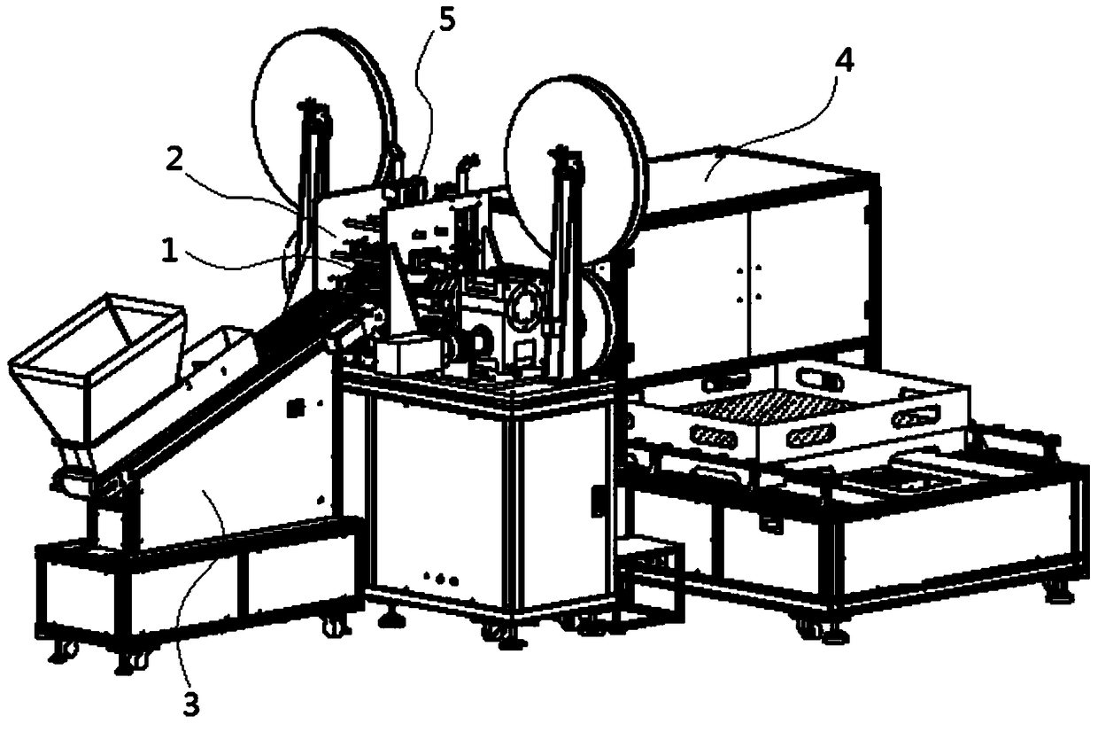
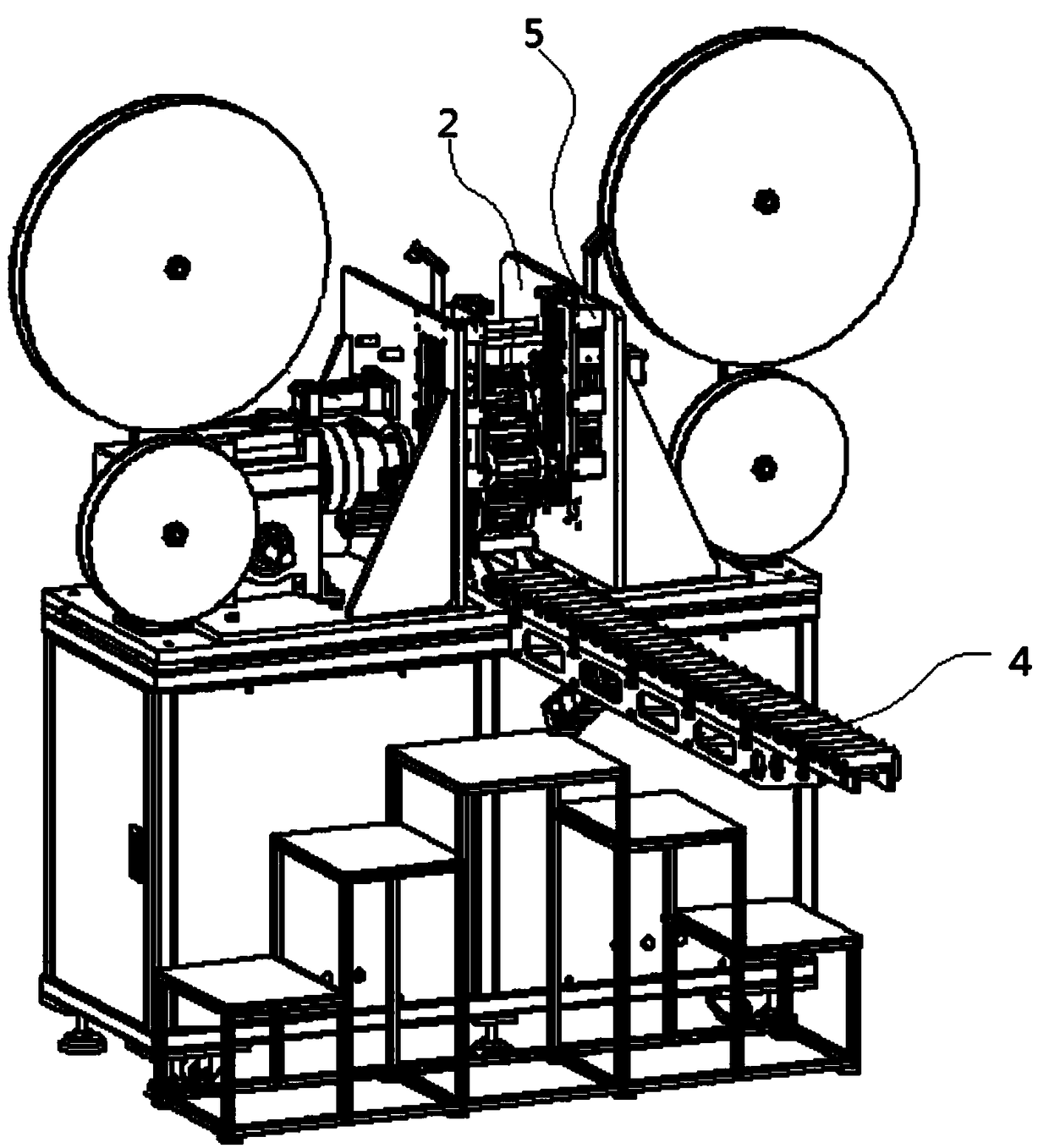
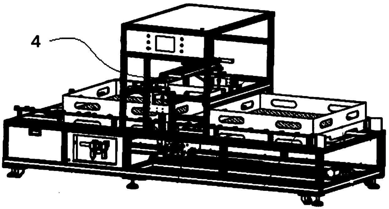
[0038] like Figures 1 to 17 As shown, a pipe end processing equipment provided by the present invention includes a multi-station clamping and conveying device 1, and a processing device for processing the end of the pipe body. One side or both sides ...


PUM


Abstract

The invention discloses pipe body end treatment equipment. The pipe body end treatment equipment comprises a multi-station clamping conveying device and machining devices for machining the ends of pipe bodies; the machining devices are arranged on one side or the two sides of the multi-station clamping conveying device; the multi-station clamping conveying device is used for clamping the pipe bodies and drives the clamped pipe bodies to move, so that the ends of the pipe bodies sequentially pass through the machining device to be machined. According to the pipe body end treatment equipment, to-be-machined pipe fittings are clamped through the multi-station clamping conveying device and conveyed between the pipe body machining devices, thus the different pipe bodies are subjected to different machining technological processes on the different stations at the same time, the pipe body end treatment equipment is compact in structure, accurate in positioning and reliable and quick in conveying, and the pipe body treatment efficiency is greatly improved.

Description

technical field [0001] The present application relates to the technical field of pipe body processing, in particular to a pipe body end processing equipment. Background technique [0002] Pipe is a necessary material for construction projects. During the actual work of the enterprise or the machining process in the factory, the end of the pipe will be expanded, crimped or edged according to the needs of actual use. End stamping folded to 90 degrees. [0003] The tube expansion process at the present stage mostly adopts a one-step operation method. When the expanded size range of the tube end is small, it can be well completed by the existing equipment, but when the expanded size range of the tube end is large When it is large, and the size and shape tolerance accuracy requirements are high, because the expansion process is too fast, the deformation of the pipe fittings in a single processing is large, which will easily lead to uneven metal extension and deformation of the p...

Claims


Application Information

Patent Timeline
Patent Type & Authority Applications(China)
IPC IPC(8): B21D19/08B21D41/02B21D43/10
CPCB21D19/08B21D41/02B21D43/105
Inventor 王健
Owner HUNAN TENYUM INTELLIGENT EQUIP
Why Eureka
Try Eureka