A safety fence for road and bridge
What is Al technical title?
Al technical title is built by PatSnap Al team. It summarizes the technical point description of the patent document.
A technology for bridges and guardrails, applied in road safety devices, roads, bridges, etc., can solve problems such as injuries to people in cars, hidden dangers of car safety, and failure to detect in time, so as to reduce hidden dangers of road safety, avoid serious deformation, avoid The effect of traffic accidents
Active Publication Date: 2020-05-22
王娟 +2
View PDF8 Cites 1 Cited by
Summary
Abstract
Description
Claims
Application Information
AI Technical Summary
This helps you quickly interpret patents by identifying the three key elements:
Problems solved by technology
Method used
Benefits of technology
Problems solved by technology
The existing safety barriers installed in the middle of the road have large gaps and lack of light blocking devices, making it easy for the lights of oncoming cars to shine on the driver's eyes, making the driver unable to see the road information clearly and causing traffic accidents. At the same time, most of the existing safety guardrails pass through rigid anti-collision devices, so that the accident car will be seriously deformed when it hits the guardrail, and the injuries to the people in the car will be aggravated. Moreover, when the existing safety guardrails are toppled over, the road Drivers on the road cannot find out in time, which brings huge safety hazards to cars on the road, so a new type of device is needed to solve the existing problems
Method used
Image
Click on the blue label to locate the original text in one second.
Reading with bidirectional positioning of images and text.
Examples
Embodiment Construction
[0026] The present invention will be further described below in conjunction with accompanying drawing:
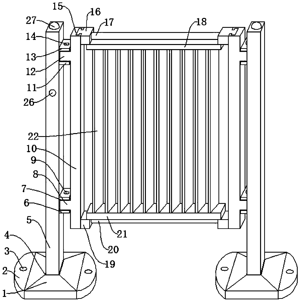
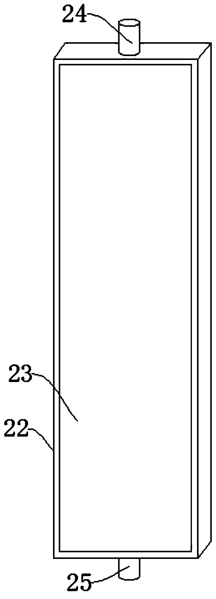
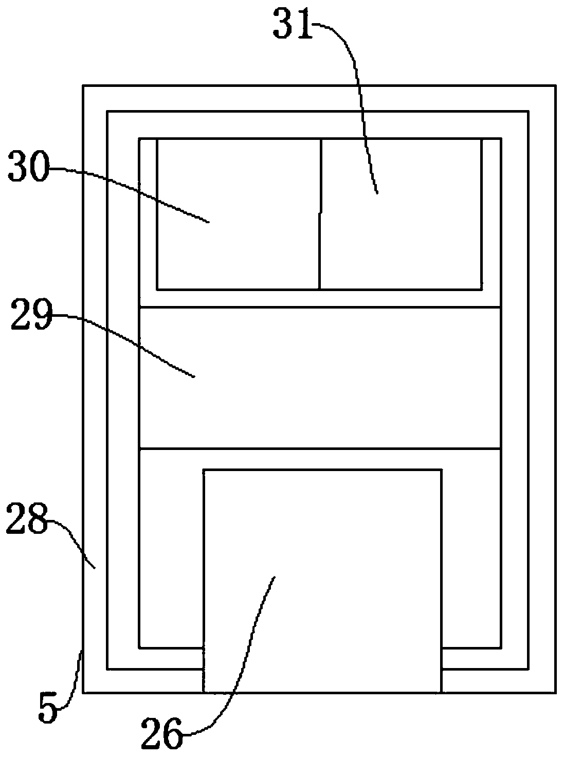
[0027] Such as Figure 1-Figure 4 As shown, a safety fence for a road bridge comprises a fixed seat 1, a fixed plate 2 and a bolt hole 3, the fixed plate 2 is provided on one side of the fixed seat 1, and the fixed plate 2 is provided with the fixed plate 2 inside. Bolt holes 3, the inside of the fixed seat 1 is provided with a slot 4, the upper side of the slot 4 is provided with a vertical rod 5, the slot 4 can fix the vertical rod 5, and the vertical rod 5 One side is provided with a No. 1 lower horizontal plate 6, and the upper side of the No. 1 lower horizontal plate 6 is provided with a lower rotating shaft 8, and the No. 1 lower horizontal plate 6 can fix the lower rotating shaft 8, and the lower rotating shaft 8 The upper side is provided with the No. 2 lower horizontal plate 7, and the inner side of the lower rotating shaft 8 is provided with a No. 1 fixing pin 9,...
PUM
Abstract
The invention discloses a safety guard railing for roads and bridges. The safety guard railing comprises a fixed seat, a fixed plate and a bolt hole. The safety guard railing has the beneficial effects that through the arrangement of a light barrier, a first rotating rod, a second rotating rod and a reflective coating, the device can effectively block the light from vehicles in the opposite direction, it is ensured that the driver can see the road information clearly, and the occurrence of traffic accidents is avoided; through the arrangement of a first lower transverse plate and a second lower transverse plate, a lower rotating shaft, a first upper transverse plate, a second upper transverse plate, an upper rotating shaft, a first fixed pin, a second fixed pin, a vertical plate, a first strong spring and a second strong spring, the car impact is flexibly buffered by the device, severe deformation of car is avoided, and the damage to the personnel in the vehicle is reduced, through thearrangement of a gravity sensor, a controller, a solar panel, a signal transmitter and a warning light, the warning light can be lighted up and give warning and the information of the fallen guard railing is sent to remote monitoring personnel for timely maintenance when the guard railing falls down, thereby reducing the road potential safety hazard.
Description
technical field [0001] The invention relates to the field of safety protection fences for roads and bridges, in particular to a safety protection fence for roads and bridges. Background technique [0002] Both sides of the expressway and both sides of the bridge are often provided with safety barriers to prevent the car from colliding to the outside of the road when an accident occurs, and to avoid greater casualties. The existing safety barriers installed in the middle of the road have large gaps and lack of light blocking devices, making it easy for the lights of oncoming cars to shine on the driver's eyes, making the driver unable to see the road information clearly and causing traffic accidents. At the same time, most of the existing safety guardrails pass through rigid anti-collision devices, so that the accident car will be seriously deformed when it hits the guardrail, and the injuries to the people in the car will be aggravated. Moreover, when the existing safety gua...
Claims
Application Information
Patent Timeline
Application Date:The date an application was filed.
Publication Date:The date a patent or application was officially published.
First Publication Date:The earliest publication date of a patent with the same application number.
Issue Date:Publication date of the patent grant document.
PCT Entry Date:The Entry date of PCT National Phase.
Estimated Expiry Date:The statutory expiry date of a patent right according to the Patent Law, and it is the longest term of protection that the patent right can achieve without the termination of the patent right due to other reasons(Term extension factor has been taken into account ).
Invalid Date:Actual expiry date is based on effective date or publication date of legal transaction data of invalid patent.