Dust removal device for road and bridge construction
A technology for dust removal devices and roads and bridges, applied in construction, cleaning methods, road surface cleaning, etc., can solve the problems of wasting human and material resources, time-consuming and laborious cleaning and dust removal, and difficulty in handling dust, and achieve the effect of saving water resources and saving human and material resources.
- Summary
- Abstract
- Description
- Claims
- Application Information
AI Technical Summary
Problems solved by technology
Method used
Image
Examples
Embodiment 1
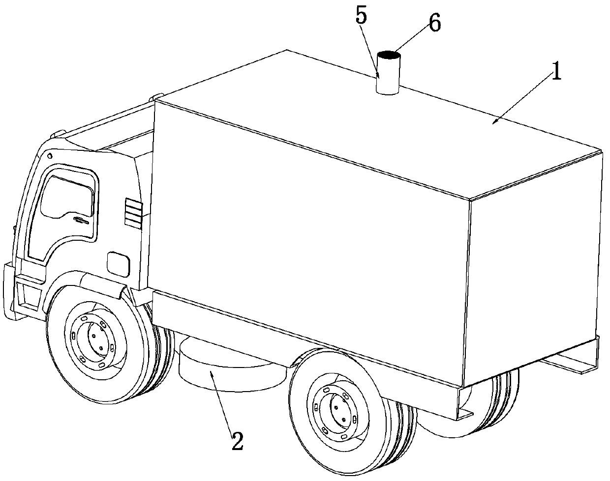
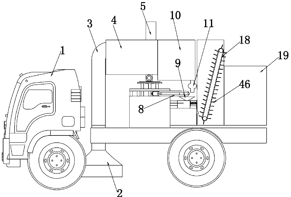
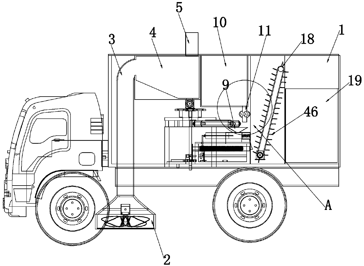
[0038]Embodiment 1, the present invention is a dust removal device for road and bridge construction, including a dust removal vehicle 1, characterized in that the lower end of the dust removal vehicle 1 is provided with a vacuum cleaner 2 with a dust suction port facing the ground, please refer to figure 1 , figure 2 with image 3 The dust suction port of the vacuum cleaner 2 has dust suction blades, the dust suction blades are controlled and driven by an internal motor, and the power supply is directly provided by the dust removal vehicle 1. The dust box 4, the dust sucked up by the vacuum cleaner 2 is collected into the dust collection box 4 through the dust suction pipe 3, please refer to figure 1 with image 3 , the upper end of the dust collection box 4 is connected with an air outlet duct 5, the interior of the air outlet duct 5 is provided with a dust filter 6, the air outlet duct 5 is used for exhaust, and the existence of the dust filter 6 is used to filter dust an...
Embodiment 2
[0047] Embodiment 2, on the basis of Embodiment 1, in order to avoid dust remaining inside the dust box 4, so that the use of the device is affected, please refer to Figure 8 , the interior of the dust collection box 4 is provided with several slopes 20 which are inclined, and the several slopes 20 are arranged so that the dust entering the interior of the dust collection box 4 gathers towards the upper end of the dust outlet hole 7 .
Embodiment 3
[0048] Embodiment 3, on the basis of Embodiment 1, in order to control the proportion of dust during compression, so that the formation of mud blocks is more effective, please refer to Figure 10 with Figure 11 , the lower end of the dust outlet hole 7 is connected with a discharge bin 21 with an opening at the front end arranged along the front and rear directions, please refer to Figure 8 , the discharge bin 21 is internally rotated along the front-rear direction and provided with a screw conveying roller 22, and the spiral conveying roller 22 is controlled and driven by a drive motor, dust falls into the inside of the discharge bin 21 through the dust outlet hole 7, and the spiral conveying roller 22 When rotating, the dust is conveyed to the front end outlet of the discharge bin 21 and falls, and the use of the screw conveying roller 22 makes the transportation of the dust more uniform. The rotating shaft of the rotating disk 23 is set in cooperation with the carriage, ...
PUM
 Abstract
Description
Claims
Application Information
 - R&D
- Intellectual Property
- Life Sciences
- Materials
- Tech Scout
- Unparalleled Data Quality
- Higher Quality Content
- 60% Fewer Hallucinations
Browse by: Latest US Patents, China's latest patents, Technical Efficacy Thesaurus, Application Domain, Technology Topic, Popular Technical Reports.
© 2025 PatSnap. All rights reserved.Legal|Privacy policy|Modern Slavery Act Transparency Statement|Sitemap|About US| Contact US: help@patsnap.com


