
A lowering speed limiting hydraulic control valve

A hydraulic control valve and speed limiting technology, which is applied in fluid pressure actuators, servo motor components, winch devices, etc., can solve the problems of large forward pressure loss, poor one-way integration, narrow applicable load range, etc., and achieve Realize the effect of low pressure loss, fast response speed, and good release speed characteristics

Active Publication Date: 2017-03-15
WUHAN MARINE MACHINERY PLANT
View PDF5 Cites 0 Cited by
  • Summary
  • Abstract
  • Description
  • Claims
  • Application Information

AI Technical Summary

Problems solved by technology

[0006] Aiming at the problems of the existing control valves that limit the lowering speed, such as large forward pressure loss, poor one-way integration, or narrow applicable load range, etc., the present invention provides a lowering speed limiting hydraulic control valve.

Method used


Image

  • A lowering speed limiting hydraulic control valve
  • A lowering speed limiting hydraulic control valve
  • A lowering speed limiting hydraulic control valve

Examples


Embodiment Construction

[0021] The present invention will be further described in detail below in conjunction with the accompanying drawings and specific embodiments.

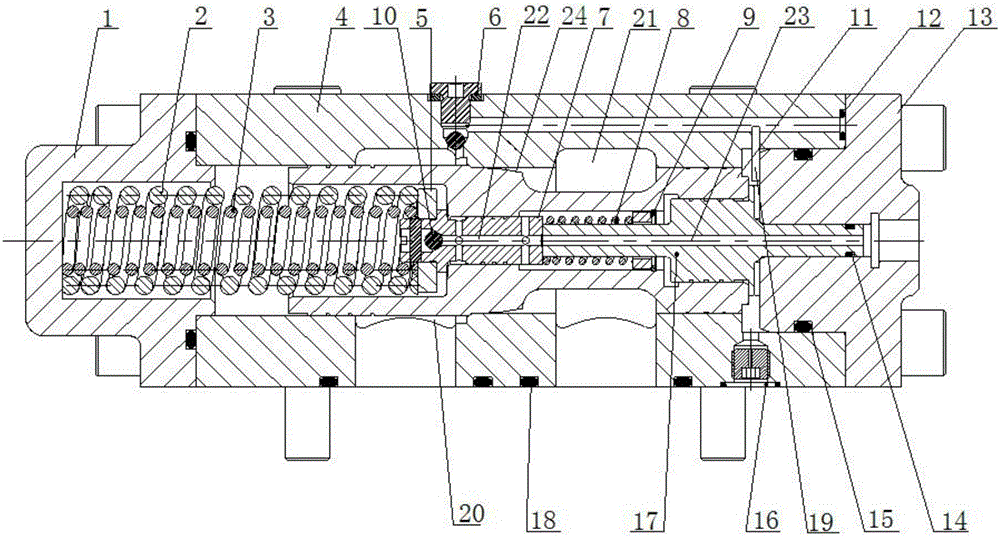
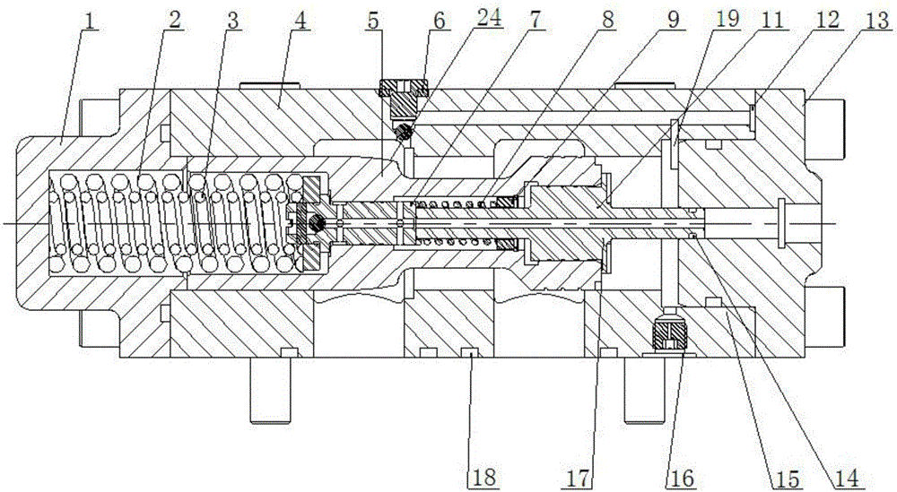
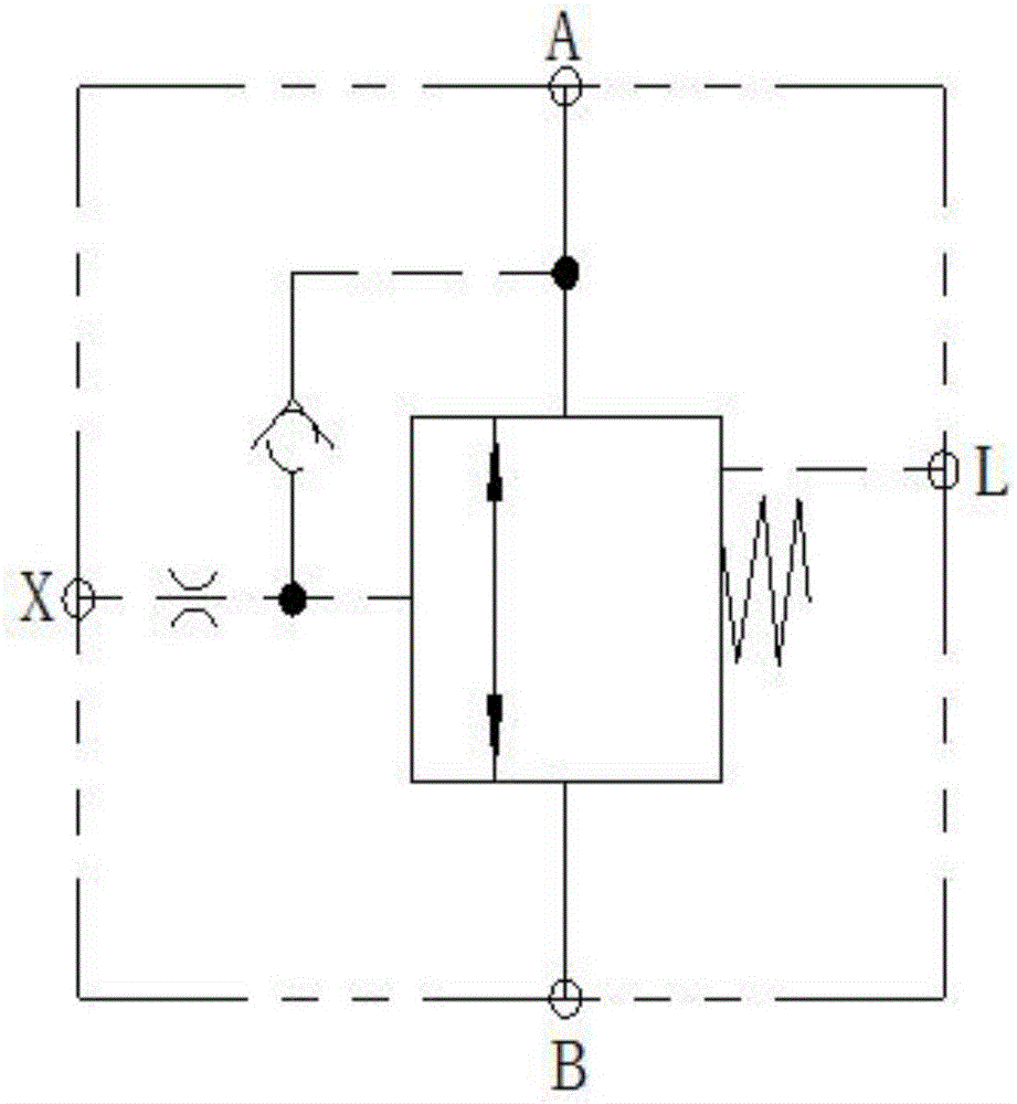
[0022] see figure 1 , a speed-limiting hydraulic control valve for lowering, including a valve body 4; the valve body 4 is provided with an oil inlet A, an oil outlet B, a remote control oil port X and a one-way valve 6. The front end of the valve body 4 is provided with a front end cover 1, and the rear end of the valve body 4 is provided with a rear end cover 13; the inner cavity of the valve body 4 is provided with a slide valve spool 11, corresponding to the oil inlet A between the valve body 4 and the slide valve. An oil chamber is formed between the valve spool 11 20. Corresponding to the oil outlet B, an oil chamber is formed between the valve body 4 and the spool valve core 11 21. The check valve 6 with oil cavity 20 connected, the spool valve core 11 cooperates with the valve body 4 to separate the oil chamber 20 ...


PUM


Abstract

Provided is a releasing speed restriction hydraulic control valve. A valve body (4) is provided with an oil inlet, an oil outlet, a check valve I (6) and a remote control oil port, a slide valve spool (11) is arranged in an inner cavity of the valve body (4), an oil chamber I (20), an oil chamber II (21) and a control oil chamber (19) are formed between the valve body (4) and the slide valve spool (11), a shoulder of the slide valve spool (11) is provided with a slope (21), a spring base (7) is arranged in an inner cavity of the slide valve spool (11), a main spring is arranged at the front end of the slide valve spool (11), a piston (17) is arranged at the rear end of the slide valve spool (11), a hollow inner hole (23) is formed in the piston (17), a small throttling hole (22) is formed in the spring base (7), and a check valve II (10) is arranged at the front end of the spring base (7). Machining difficulty is reduced, and forward low pressure loss is achieved; the reverse work releasing speed restriction characteristic is good, and the response speed is high in the closing process.

Description

technical field [0001] The present invention relates to a hydraulic control valve, more specifically to a hydraulic control valve for lowering speed limitation. Background technique [0002] The hydraulic lifting device usually has a working condition, which requires the load to be hoisted up quickly, and at the same time, the load can be lowered smoothly. In the hydraulic system of this hydraulic lifting device, hydraulic motors or hydraulic cylinders are generally used to perform related movements; there is generally no problem when hoisting the load up, but when descending, the hydraulic motor or cylinder will be affected. Due to the gravity of the load, if the corresponding force against gravity cannot be generated, the hydraulic motor or cylinder will continue to accelerate and move downward under the action of gravity, then the speed of the load will become faster and faster when it is lowered, and finally it cannot be controlled. , and the relevant equipment cannot b...

Claims


Application Information

Patent Timeline
Patent Type & Authority Patents(China)
IPC IPC(8): F15B13/02
CPCB66D1/48F15B13/02
Inventor 方敏吴建磊胡发国司小冬赵天梁
Owner WUHAN MARINE MACHINERY PLANT
Learn More