Power cycle testing method and device for intelligent power module

An intelligent power module and power cycle technology, which is applied in measurement devices, environment/reliability testing, circuit breaker testing, etc., can solve problems such as the inability to accurately simulate the working conditions of intelligent power modules, and achieve simple and efficient judgment methods. The effect of ensuring accuracy

Active Publication Date: 2019-03-22
美垦半导体技术有限公司
View PDF7 Cites 2 Cited by
  • Summary
  • Abstract
  • Description
  • Claims
  • Application Information

AI Technical Summary

Problems solved by technology

[0004] The embodiment of the present application provides a power cycle test method and device for an intelligent power module, which solves the problem in the prior art that the actual working conditions of the intelligent power The cycle aging test method can accurately and effectively simulate the actual working conditions of the intelligent power module

Method used


Image

  • Power cycle testing method and device for intelligent power module
  • Power cycle testing method and device for intelligent power module
  • Power cycle testing method and device for intelligent power module

Examples


Embodiment Construction

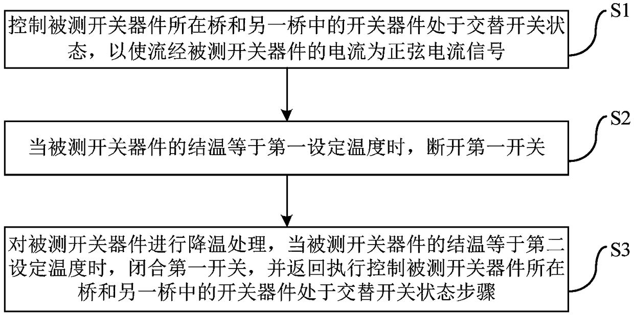
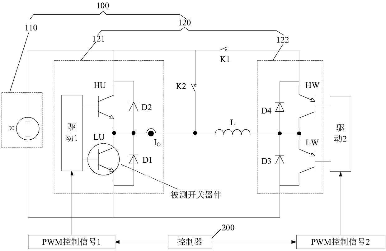
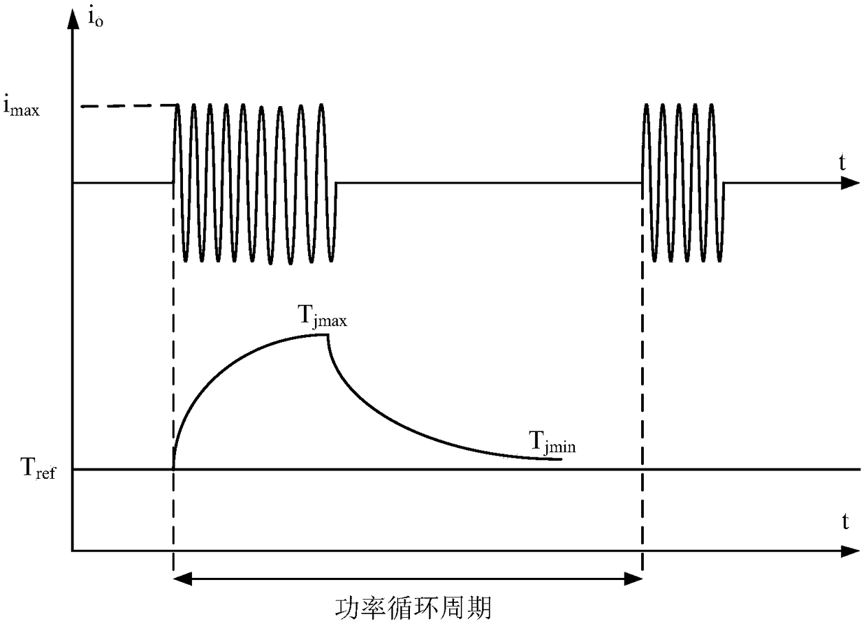
[0028] This application periodically provides a sinusoidal current signal to the switch device under test, and controls the junction temperature of the switch device under test accordingly, so as to realize the AC power cycle of the smart power module, thereby accurately and effectively simulating the power of the smart power module. actual working conditions.

[0029] In order to better understand the above-mentioned technical solutions, exemplary embodiments of the present disclosure will be described in more detail below with reference to the accompanying drawings. Although exemplary embodiments of the present disclosure are shown in the drawings, it should be understood that the present disclosure may be embodied in various forms and should not be limited by the embodiments set forth herein. Rather, these embodiments are provided for more thorough understanding of the present disclosure and to fully convey the scope of the present disclosure to those skilled in the art.

...


PUM


Abstract

The application discloses a power cycle testing method and device for an intelligent power module. The intelligent power module comprises a constant current source and a plurality of bridges connectedin parallel at two ends of the constant current source, wherein the bridge where a tested switch device is positioned is connected with the other bridge through inductance; and the first end of the bridge where the tested switch device is connected with the first end of the other bridge through a first switch. The method includes controlling the tested switch device in the bridge where the testedswitch device is positioned and the switch device in the other bridge to be in an alternating switching state, so as to enable the current flowing through the tested switch device to be a sinusoidalcurrent signal; when the junction temperature of the tested switch device is equal to the first set temperature, turning off the first switch; cooling the tested switch device; and when the junction temperature of the tested switch device is equal to the second set temperature, closing the first switch, and returning to the step of controlling the tested switch device in the bridge where the tested switch device is positioned and the switch device in the other bridge to be in the alternating switch state. Therefore, the actual working condition of the intelligent power module can be accuratelyand effectively simulated.

Description

technical field [0001] The present application relates to the technical field of intelligent power modules, in particular to a power cycle test method for an intelligent power module and a power cycle test device for an intelligent power module. Background technique [0002] The power cycle accelerated aging experiment is to apply power to the switching device through conduction or high-frequency on-off, resulting in heat loss, causing the temperature of the switching device to fluctuate greatly periodically, forming thermal shock, and generating thermoelectric stress, thereby accelerating the aging process. Its purpose is to understand the relationship between the aging and failure mechanisms of intelligent power modules in a short period of time, and to discover the weak links of switching device packaging, which will help manufacturers to improve and optimize from the material and structure levels. At the same time, it can be used to describe intelligent power modules. Ac...

Claims


Application Information

Patent Timeline
Patent Type & Authority Applications(China)
IPC IPC(8): G01R31/00G01R31/327
CPCG01R31/00G01R31/003G01R31/327
Inventor 马博斌冯宇翔
Owner 美垦半导体技术有限公司
Why Eureka
Try Eureka