Light source direction positioning device

A light source direction and positioning device technology, which is applied in the direction of devices with multi-detectors, direction finders using electromagnetic waves, photometry using electric radiation detectors, etc., can solve the problems of light source direction recognition and orientation. Solutions and other issues

Pending Publication Date: 2019-03-22
CIG SHANGHAI
View PDF4 Cites 6 Cited by
  • Summary
  • Abstract
  • Description
  • Claims
  • Application Information

AI Technical Summary

Problems solved by technology

[0003] The technical problem to be solved by the present invention is to provide a light source direction positioning device in order to overcome the defect that there is no good solution for the problem of identification and orientation of the light source's illumination direction in the prior art

Method used


Image

  • Light source direction positioning device
  • Light source direction positioning device

Examples


Embodiment Construction

[0024] The present invention is further illustrated below by means of examples, but the present invention is not limited to the scope of the examples.

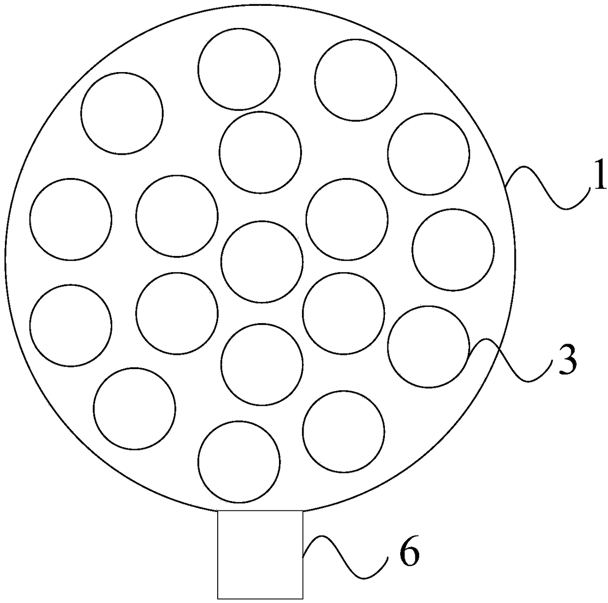
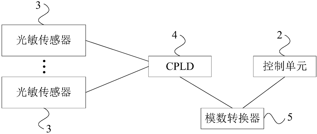
[0025] Such as Figure 1-2 As shown, the light source direction positioning device of the present invention includes a spherical body 1, a control unit 2 and a plurality of photosensitive sensors 3;

[0026] The surface of the spherical body 1 is provided with a plurality of grooves, and the photosensitive sensor 3 is arranged in each groove, specifically, a photosensitive sensor 3 is arranged in each groove, and the control unit 2 is arranged on the spherical body. Inside the main body 1, the control unit 2 is used to electrically connect with the plurality of photosensitive sensors 3;

[0027] The photosensitive sensor 3 is used to detect the light signal sent by the external light source, and after generating the detection signal, send the detection signal to the control unit 2. The photosensitive sensor 3 can specifically...


PUM


Abstract

The invention discloses a light source direction positioning device, which comprises a spherical main body, a control unit and a plurality of photosensitive sensors, wherein a plurality of grooves areformed in the surface of the spherical main body; each photosensitive sensor is arranged in each of the grooves; the control unit is disposed inside the spherical main body; the control unit is electrically connected with the plurality of photosensitive sensors; the photosensitive sensors are configured to detect a light signal emitted by an external light source, generate a detection signal, andthen send the detection signal to the control unit; and the control unit is configured to acquire a light intensity value detected by each photosensitive sensor according to the detection signal, anddetermine a light source direction of the external light source according to a magnitude of the light intensity value. According to the light source direction positioning device, by the arrangement of the photosensitive sensors on the surface of the spherical main body and then positioning of the direction of illumination of the light source by using the light intensity value detected by the photosensitive sensors, the direction of illumination of the light source in each direction can be positioned.

Description

technical field [0001] The invention relates to a light source direction positioning technology, in particular to a light source direction positioning device. Background technique [0002] In the prior art, there is no good solution to the identification and orientation of the illumination direction of the light source for the time being, resulting in the inability to orient the illumination direction in time, and thus the inability to make good use of light sources such as sunlight. Contents of the invention [0003] The technical problem to be solved by the present invention is to provide a light source direction positioning device in order to overcome the defect that there is no good solution to the problem of identification and orientation of the light source's illumination direction in the prior art. [0004] The present invention solves the above technical problems through the following technical solutions: [0005] The invention provides a light source direction po...

Claims


Application Information

Patent Timeline
Patent Type & Authority Applications(China)
IPC IPC(8): G01S3/78G01J1/42
CPCG01J1/4228G01S3/78
Inventor 袁泉牛频
Owner CIG SHANGHAI
Why Eureka
Try Eureka