Self-mounting three-cylinder combined multistage variable amplitude device

A self-installation, oil cylinder technology, applied in cranes and other directions, can solve the problems of low transfer efficiency of large-tonnage cranes, inability to realize one-time installation of the jib, affecting the stability and safety of the jib, etc., to improve the transfer efficiency, Simple structure and easy processing effect

Active Publication Date: 2019-03-26
XCMG HYDRAULICS CO LTD
View PDF6 Cites 3 Cited by
  • Summary
  • Abstract
  • Description
  • Claims
  • Application Information

AI Technical Summary

Problems solved by technology

[0004] 1. It needs to assist external hoisting equipment, which can only realize the small-angle rotation of the jib, and cannot be automatically displaced and installed;
[0005] 2. Due to the limited installation space, the existing turning device cannot be processed too large, and it is impossible to realize large-angle turning and one-time installation of the auxiliary arm;
[0006] 3. The existing luffing device has no automatic locking and fixing function when the jib is at high altitude, which causes the luffing device to swing / shake at high altitude, which affects the stability and safety of the jib and reduces the hoisting accuracy;
[0007] These shortcomings lead to low transfer efficiency of large-tonnage cranes and extremely high transfer costs

Method used


Image

  • Self-mounting three-cylinder combined multistage variable amplitude device
  • Self-mounting three-cylinder combined multistage variable amplitude device
  • Self-mounting three-cylinder combined multistage variable amplitude device

Examples


Embodiment Construction

[0025] The following is a specific embodiment of the present invention, and the present invention will be further described in conjunction with the accompanying drawings.

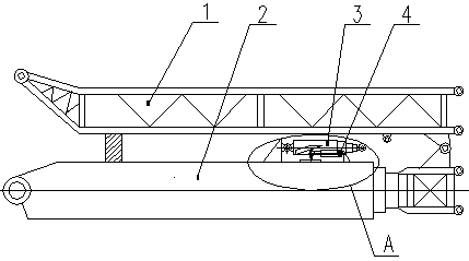
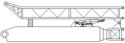
[0026] combine Figure 1 to Figure 4 As shown, a self-installing three-cylinder combined multi-stage luffing device includes a boom 2 and a jib 1 hinged on the boom 2 .

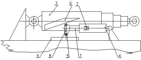
[0027] The luffing main cylinder 3 is a multi-stage cylinder, the bottom end of the luffing main cylinder 3 is hinged with the boom 2, the piston rod end of the luffing main cylinder 3 is provided with a pin hole, and the auxiliary arm 1 is fixed with a pin hole matching the pin hole seat. The pin hole on the piston rod end of the luffing master oil cylinder 3 is detachably hinged with the pin hole seat on the auxiliary arm 1 through a pin shaft. Symmetrically arranged wedge-shaped guide rails 6 and roller slots 7 are fixed on both sides of the luffing master oil cylinder 3 .

[0028] There are two auxiliary displacement oil cylinders 4...


PUM


Abstract

The invention discloses a self-mounting three-cylinder combined multistage variable amplitude device, and belongs to the technical field of engineering hoisting machinery. The self-mounting three-cylinder combined multistage variable amplitude device comprises a boom, an auxiliary jib, a variable amplitude main cylinder and auxiliary displacement cylinders, wherein one end of the variable amplitude main cylinder is hinged to the boom; the other end of the variable amplitude main cylinder is detachably hinged to the auxiliary jib; one ends of the auxiliary displacement cylinders are hinged to the boom; rollers are mounted at the other ends of the auxiliary displacement cylinders; wedge-shaped guide rails and roller clamping grooves are fixed on the variable amplitude main cylinder; when theauxiliary displacement cylinders stretch out, the rollers are propped against the wedge-shaped guide rollers; and when the auxiliary displacement cylinders retreat, free ends of the auxiliary displacement cylinders enter the roller clamping grooves. According to the self-mounting three-cylinder combined multistage variable amplitude device, requirements of small mounting interval and large span are met, 0-90-degree large-angle automatic rotation of the auxiliary jib is achieved, the auxiliary jib is automatically mounted without external hoisting equipment, an automatic locking fixing function of the variable amplitude main cylinder is achieved, the variable amplitude device is prevented from swinging / shaking in high air, stability and safety of the auxiliary jib are improved, and hoisting precision is improved.

Description

technical field [0001] The invention relates to the technical field of engineering hoisting machinery, in particular to a self-installing three-cylinder combined multi-stage luffing device used on a boom. Background technique [0002] In order to achieve the hoisting height and distance, the boom of the large-tonnage crane can reach 7 knots, but in order to meet the extreme working conditions, the main engine also has a lattice arm (commonly known as the jib) to increase the arm length and complete the ultra-long-distance hoisting. For example, when installing wind power, it is necessary to unfold the auxiliary arm folded on the main arm. [0003] The existing jib mainly relies on auxiliary hoisting equipment and is manually installed. The disadvantages are: [0004] 1. It needs to assist external hoisting equipment, which can only realize the small-angle rotation of the jib, and cannot be automatically displaced and installed; [0005] 2. Due to the limited installation s...

Claims


Application Information

Patent Timeline
Patent Type & Authority Applications(China)
IPC IPC(8): B66C23/693
CPCB66C23/705
Inventor 褚桂君刘朋金全明张虹源张靖靖陈向兵郑圆圆
Owner XCMG HYDRAULICS CO LTD
Why Eureka
Try Eureka