A VAD sintered optical fiber preform master rod stretching device and stretching method
A technology of optical fiber prefabricated rods and stretching devices, which is applied in the direction of manufacturing tools and glass manufacturing equipment, can solve the problems of increased brittleness of lead rods, large demand for lead rods, smashing rods, etc., and achieve reduced man-hours, good geometric shape uniformity, Even heating effect
- Summary
- Abstract
- Description
- Claims
- Application Information
AI Technical Summary
Problems solved by technology
Method used
Image
Examples
Embodiment 1
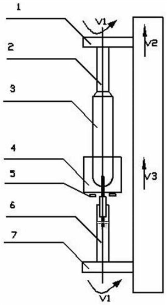
[0033] This embodiment provides a VAD sintered optical fiber preform master rod drawing device, such as figure 1 As shown, it includes an upper chuck 1, a stretching furnace 4, a caliper 5, and a lower chuck 7 arranged in sequence along the vertical direction;
[0034] The upper chuck 1 can be rotated and lifted, and the upper chuck 1 is clamped with an upper drawing rod 2 welded on the upper end of the optical fiber preform master rod 3;
[0035] The stretching furnace 4 can be lifted;
[0036] The lower chuck 7 can be rotated, and the lower chuck 7 clamps the lower drawing rod 6, and the VAD deposition target head at the lower end of the optical fiber preform master rod 3 is fixed in the lower drawing rod 6;
[0037] The caliper 5 is connected with the stretching furnace 4 and is used to measure the diameter of the optical fiber preform mother bar 3 at each position section, and a graphite insulation ring for heat insulation is arranged above the caliper 5 .
[0038] When ...
Embodiment 2
[0044] In this embodiment, the optical fiber preform master bar 3 with an average diameter of 83 mm and a length of 600 mm prepared by stretching the VAD process is welded to the upper end of the optical fiber preform master bar 3 with a diameter of 60 mm and a length of 1000 mm. ), the lower end of the optical fiber preform rod 3 retains the target head when VAD deposits and hangs the rod.
[0045] The stretching method of the optical fiber preform rod 3 is:
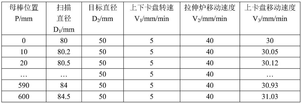
[0046] The upper drawing rod 2 welded to the upper end of the optical fiber preform master rod 3 is fixed and clamped by the upper chuck 1, and the optical fiber preform master rod 3 is vertically passed through the drawing furnace 4 through the lifting of the upper chuck 1 , and insert the target head of the optical fiber preform master rod 3 into the opening of the down-drawing lead rod 6 (preferably a quartz lead rod), and insert the target head of the optical fiber preform rod master rod 6 into the radial direction ...
Embodiment 3
[0056] In this embodiment, the optical fiber preform master bar 3 with an average diameter of 100mm and a length of 450mm prepared by the VAD process is stretched. ), the lower end of the optical fiber preform rod 3 retains the target head when VAD deposits and hangs the rod.
[0057] The stretching method of the optical fiber preform rod 3 is:
[0058] The upper drawing rod 2 welded to the upper end of the optical fiber preform master rod 3 is fixed and clamped by the upper chuck 1, and the optical fiber preform master rod 3 is vertically passed through the drawing furnace 4 through the lifting of the upper chuck 1 , and insert the target head of the optical fiber preform master rod 3 into the opening of the down-drawing lead rod 6 (preferably a quartz lead rod), and insert the target head of the optical fiber preform rod master rod 6 into the radial direction of the down-drawing lead rod 6 Bolt fastening in the opening;
[0059] Move the caliper 5 at the lower end of the s...
PUM
| Property | Measurement | Unit |
|---|---|---|
| diameter | aaaaa | aaaaa |
| diameter | aaaaa | aaaaa |
Abstract
Description
Claims
Application Information
 - R&D
- Intellectual Property
- Life Sciences
- Materials
- Tech Scout
- Unparalleled Data Quality
- Higher Quality Content
- 60% Fewer Hallucinations
Browse by: Latest US Patents, China's latest patents, Technical Efficacy Thesaurus, Application Domain, Technology Topic, Popular Technical Reports.
© 2025 PatSnap. All rights reserved.Legal|Privacy policy|Modern Slavery Act Transparency Statement|Sitemap|About US| Contact US: help@patsnap.com


