Stretching device and stretching method for VAD sintered optical fiber prefabricated base bar

An optical fiber preform and stretching device technology, which is applied to manufacturing tools, glass manufacturing equipment, etc., can solve the problems of increased lead brittleness, large lead demand, and broken rods, and achieves reduced man-hours, good geometric shape uniformity, Even heating effect

Active Publication Date: 2019-03-26
TONGDING INTERCONNECTION INFORMATION CO LTD +1
View PDF7 Cites 4 Cited by
  • Summary
  • Abstract
  • Description
  • Claims
  • Application Information

AI Technical Summary

Problems solved by technology

Therefore, the drawing process has a relatively large demand for the guide rod, and the brittleness of the guide rod increases after the number of reuses increases, which easily causes the risk of dropping or smashing the rod during the stretching process

Method used


Image

  • Stretching device and stretching method for VAD sintered optical fiber prefabricated base bar
  • Stretching device and stretching method for VAD sintered optical fiber prefabricated base bar
  • Stretching device and stretching method for VAD sintered optical fiber prefabricated base bar

Examples


Embodiment 1

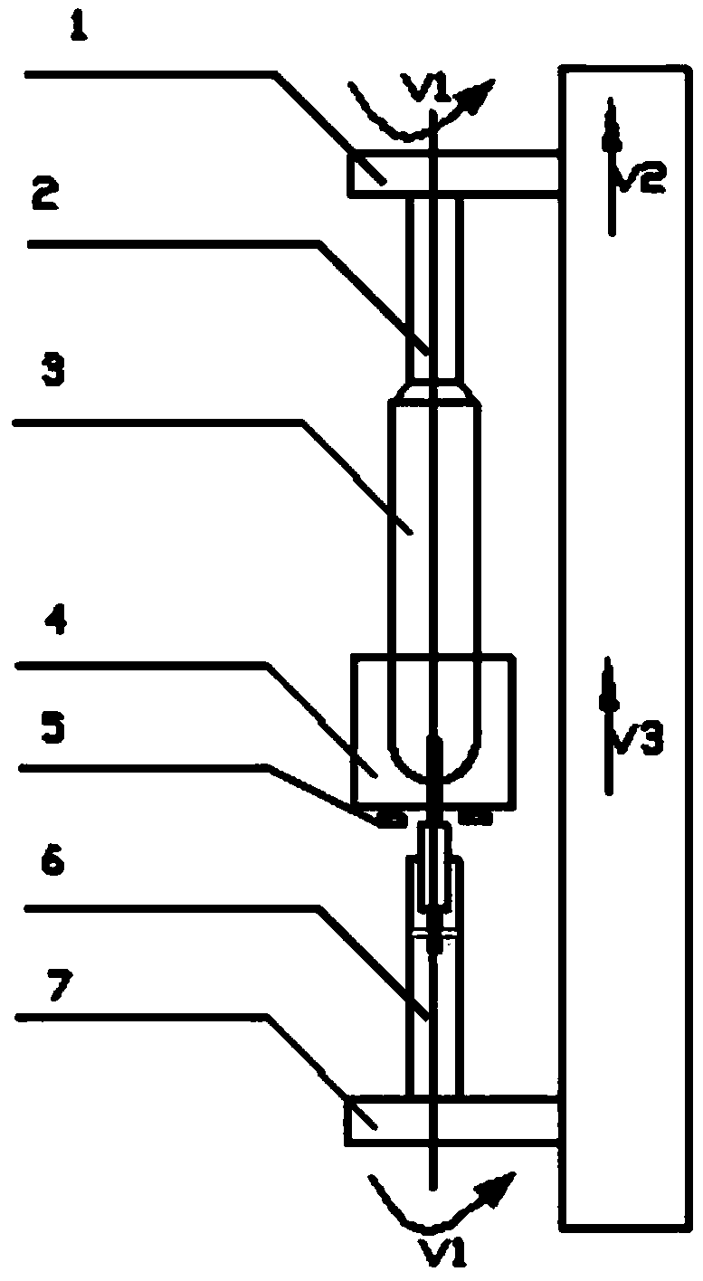
[0033] This embodiment provides a VAD sintered optical fiber preform master rod drawing device, such as figure 1 As shown, it includes an upper chuck 1, a stretching furnace 4, a caliper 5, and a lower chuck 7 arranged in sequence along the vertical direction;

[0034] The upper chuck 1 can be rotated and lifted, and the upper chuck 1 is clamped with an upper drawing rod 2 welded on the upper end of the optical fiber preform master rod 3;

[0035] The stretching furnace 4 can be lifted;

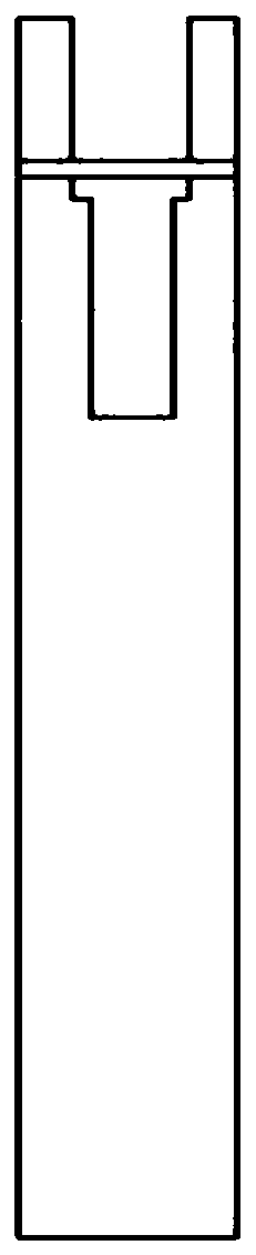
[0036] The lower chuck 7 can be rotated, and the lower chuck 7 clamps the lower drawing rod 6, and the VAD deposition target head at the lower end of the optical fiber preform master rod 3 is fixed in the lower drawing rod 6;

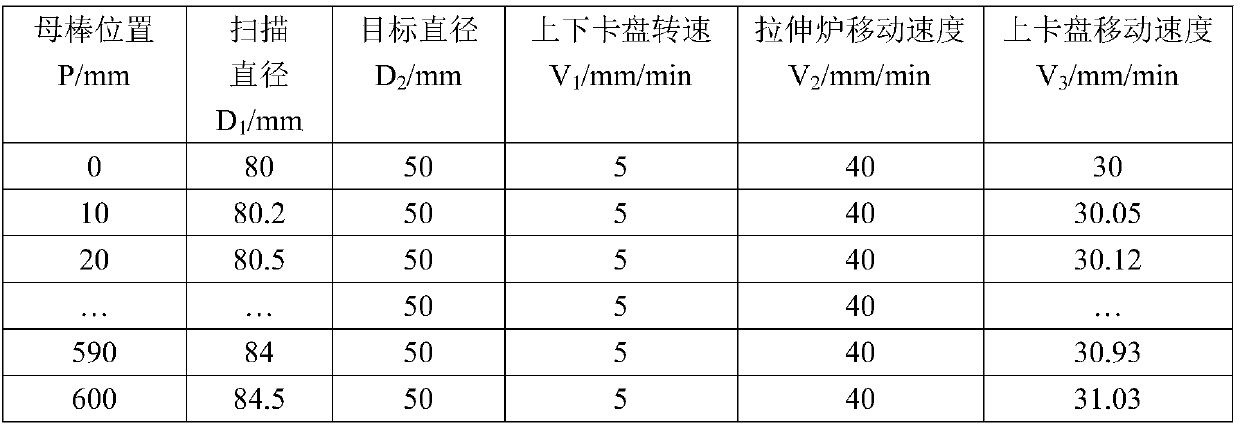
[0037] The caliper 5 is connected with the stretching furnace 4 and is used to measure the diameter of the optical fiber preform mother bar 3 at each position section, and a graphite insulation ring for heat insulation is arranged above the caliper 5 .

[0038] When ...

Embodiment 2

[0044] In this embodiment, the optical fiber preform master bar 3 with an average diameter of 83 mm and a length of 600 mm prepared by stretching the VAD process is welded to the upper end of the optical fiber preform master bar 3 with a diameter of 60 mm and a length of 1000 mm. ), the lower end of the optical fiber preform rod 3 retains the target head when VAD deposits and hangs the rod.

[0045] The stretching method of the optical fiber preform rod 3 is:

[0046] The upper drawing rod 2 welded to the upper end of the optical fiber preform master rod 3 is fixed and clamped by the upper chuck 1, and the optical fiber preform master rod 3 is vertically passed through the drawing furnace 4 through the lifting of the upper chuck 1 , and insert the target head of the optical fiber preform master rod 3 into the opening of the down-drawing lead rod 6 (preferably a quartz lead rod), and insert the target head of the optical fiber preform rod master rod 6 into the radial direction ...

Embodiment 3

[0056] In this embodiment, the optical fiber preform master bar 3 with an average diameter of 100mm and a length of 450mm prepared by the VAD process is stretched. ), the lower end of the optical fiber preform rod 3 retains the target head when VAD deposits and hangs the rod.

[0057] The stretching method of the optical fiber preform rod 3 is:

[0058] The upper drawing rod 2 welded on the upper end of the optical fiber preform master rod 3 is fixed and clamped by the upper chuck 1, and the optical fiber preform master rod 3 is vertically passed through the drawing furnace 4 through the lifting of the upper chuck 1 , and insert the target head of the optical fiber preform master rod 3 into the opening of the down-drawing lead rod 6 (preferably a quartz lead rod), and insert the target head of the optical fiber preform rod master rod 3 into the radial direction of the down-drawing lead rod 6 Bolt fastening in the opening;

[0059] Move the caliper 5 at the lower end of the s...


PUM

PropertyMeasurementUnit
diameteraaaaaaaaaa
diameteraaaaaaaaaa

Abstract

The invention relates to a stretching device and a stretching method for a VAD sintered optical fiber prefabricated base bar. The stretching device comprises an upper chuck, a stretching furnace and alower chuck which are successively arranged along a vertical direction. The stretching method comprises the following steps: measuring and collecting diameter of the optical fiber prefabricated basebar on each position; calculating an upward moving rate of the upper chuck and confirming the upward moving rate of the upper chuck according to the required diameter of stretched core rod, the upwardmoving rate of the stretching furnace and the diameter of the stretched optical fiber prefabricated base bar; synchronously rotating the upper chuck and the lower chuck at a same rotation rate beforeheating and stretching, and then starting to heat the lower end of the optical fiber prefabricated base bar by starting the stretching furnace; controlling the upper chuck to calculate the upward moving rate and stretching the optical fiber prefabricated base bar, thereby forming a core rod. According to the invention, stretching quality and efficiency of optical fiber prefabricated base bar canbe guaranteed, dosage of guiding rod can be reduced and welding times of guiding rod can be reduced.

Description

technical field [0001] The invention relates to a VAD sintered optical fiber preform mother rod stretching device and a stretching method, belonging to the technical field of optical fiber preform preparation. Background technique [0002] Optical fiber preforms are the key raw materials for optical fiber cables. For a long time, the preform manufacturing technology has been monopolized by foreign companies, which has led to my country's heavy dependence on imports of optical fiber preforms and hindered the development of my country's optical communication network. With the continuous expansion of the scale of my country's optical communication network, the demand for preforms is increasing rapidly, and the development of high-quality preforms has become an important topic in the field of optical communications. However, the production technology and process requirements of the preform are very high, and the capital investment is large, so that many domestic optical fiber pr...

Claims


Application Information

Patent Timeline
Patent Type & Authority Applications(China)
IPC IPC(8): C03B37/025
CPCC03B37/025
Inventor 沈小平梁伟蒋锡华何炳刘建中王祥朱志远
Owner TONGDING INTERCONNECTION INFORMATION CO LTD
Why Eureka
Try Eureka