
Optical performance detecting device

A technology for optical performance and detection equipment, which is applied in the testing of optical performance, optical instrument testing, branch equipment, etc., can solve the problems of high cost and low detection efficiency, and achieve a small space occupation rate, reduce production costs, and compact internal structure. Effect

Pending Publication Date: 2019-03-26
SHENZHEN ITC TECH
View PDF0 Cites 0 Cited by
  • Summary
  • Abstract
  • Description
  • Claims
  • Application Information

AI Technical Summary

Problems solved by technology

[0004] The object of the present invention is to provide a kind of optical performance detection equipment, to solve the technical problems of low detection efficiency and high cost in the prior art

Method used


Image

  • Optical performance detecting device
  • Optical performance detecting device
  • Optical performance detecting device

Examples


Embodiment Construction

[0085] In order to make the technical problems, technical solutions and beneficial effects to be solved by the present invention clearer, the present invention will be further described in detail below in conjunction with the accompanying drawings and embodiments. It should be understood that the described embodiments are some, not all, embodiments of the present invention. Based on the described embodiments of the present invention, all other embodiments obtained by persons of ordinary skill in the art without creative efforts shall fall within the protection scope of the present invention.

[0086] In order to enable those skilled in the art to better understand the technical solutions of the present invention, the implementation of the present invention will be described in detail below in conjunction with specific drawings.

[0087] For the convenience of description, the "front", "rear", "left", "right", "upper" and "lower" referred to in the following are consistent with...


PUM


Abstract

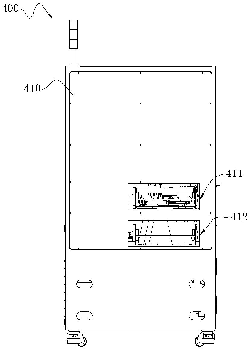
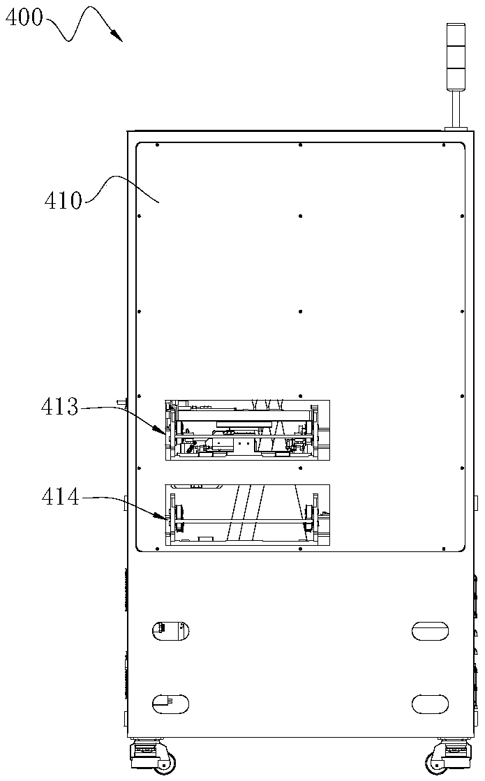
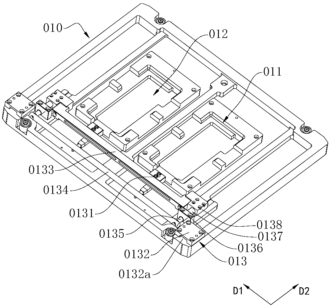
The invention, which relates to the technical field of optical detection of a camera module, provides an optical performance detecting device comprising a box body, a feeding and discharging device, and an optimal performance detecting device for detecting the optical performance of a mobile terminal. The feeding and discharging device includes an upper conveying unit and a lower conveying unit that are arranged up and down in a direction perpendicular to the bottom of the box body. The upper conveying unit is used for conveying a terminal carrying disc loaded with a to-be-tested mobile terminal; and the mobile terminal is placed on the terminal carrying disc and is supported by the terminal carrying disc. The lower conveying unit is used for conveying the idle terminal carrying disc in adirection opposite to the conveying direction of the upper conveying unit. The upper conveying unit includes a detection positioning bracket and an upper conveying mechanism that is arranged in the detection positioning bracket and is used for moving the terminal carrying disc; and the detection positioning bracket is provided with a plug assembly connected electrically with the mobile terminal. Compared with the prior art, the optical performance detecting device has the following advantages: the internal structure becomes compact; the spatial occupation rate is reduced; the testing efficiency is greatly improved; and the production cost is lowered.

Description

technical field [0001] The invention relates to the technical field of optical detection of camera modules, in particular to an optical performance detection device. Background technique [0002] With the rapid development of smart phones in recent years, TOF (Time Of Flight, hereinafter collectively referred to as TOF) imaging technology has been applied to smart phones to achieve 3D depth imaging. The TOF sensor emits modulated near-infrared light, which is reflected after encountering an object. The sensor calculates the distance of the object to be photographed by calculating the infrared light emission and reflection time difference or phase difference to generate depth information, and further combines traditional contact shooting , so as to present the three-dimensional outline of the object in a graphical way with different colors representing different distances. [0003] At present, the imaging quality requirements for mobile phone cameras are getting higher and h...

Claims


Application Information

Patent Timeline
IPC IPC(8): G01M11/00G01M11/02H04M1/24H04N17/00
CPCH04M1/24H04N17/002G01M11/00
Inventor 黄培坤王琦琳刘志发李天潮
Owner SHENZHEN ITC TECH
Features
  • Generate Ideas
  • Intellectual Property
  • Life Sciences
  • Materials
  • Tech Scout
  • Unparalleled Data Quality
  • Higher Quality Content
  • 60% Fewer Hallucinations
Learn More