Chicken feeding device

A technology for installing troughs and barrels, which is applied to heating devices, poultry farming, lighting and heating equipment, etc. It can solve the problems of feeding free-range chickens, increasing the labor intensity of breeders, and complicated workmanship, so as to avoid mutual competition Food, simple structure, reduce the effect of labor intensity

Pending Publication Date: 2019-03-29
FOSHAN UNIVERSITY
View PDF0 Cites 0 Cited by
  • Summary
  • Abstract
  • Description
  • Claims
  • Application Information

AI Technical Summary

Problems solved by technology

[0002] For free-range chicken farmers, sometimes the feed in the feeding device or the remaining residue of some feed will not be eaten every 2-3 days, and sometimes there will be a problem with the leftover feed. Wet feed will lead to mold growth or Many other bacteria, if the chicken eats this kind of feed for a long time, it may cause death, and pouring out the moldy feed will also cause waste. In order to prevent the chickens from competing for food, the existing feeding device is provided with multiple feeding troughs on the feeding device. However, when the breeder puts in the feed, he needs to put in each feeding trough, which greatly increases the labor intensity of the breeder and brings troubles to the feed feeding of free-range chickens. Although there are smart feeding devices at present, the workmanship is complicated. It is applied to large-scale chicken farms, and the cost is relatively high for free-range chicken farmers. It is difficult to apply it to large-scale free-range farmers

Method used


Image

  • Chicken feeding device
  • Chicken feeding device

Examples


Embodiment Construction

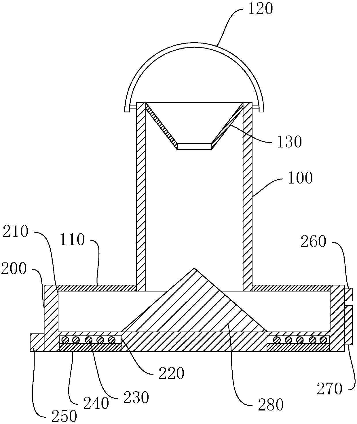
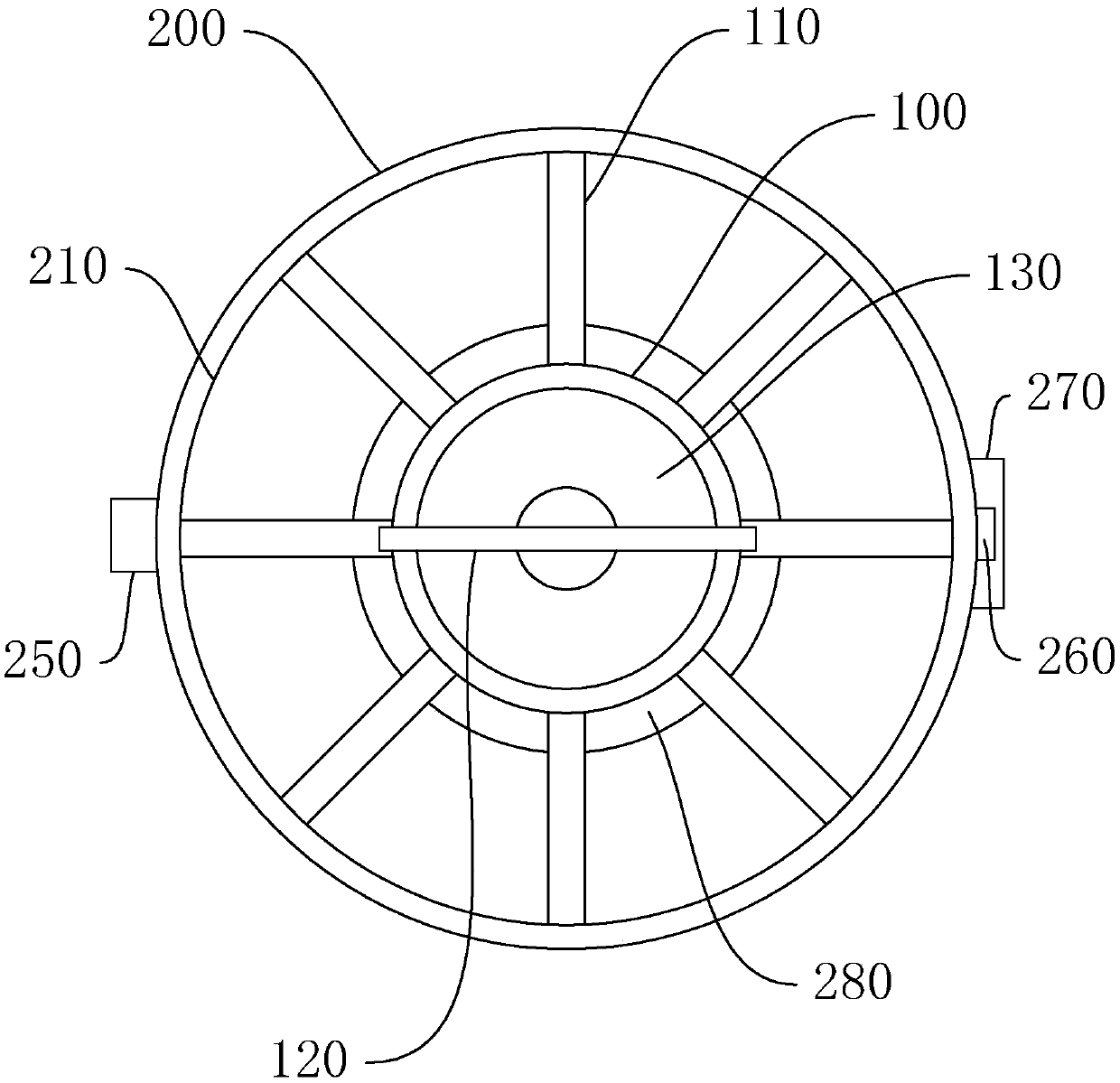
[0017] The idea, specific structure and technical effects of the present invention will be clearly and completely described below in conjunction with the embodiments and accompanying drawings, so as to fully understand the purpose, features and effects of the present invention. Apparently, the described embodiments are only some of the embodiments of the present invention, rather than all of them. Based on the embodiments of the present invention, other embodiments obtained by those skilled in the art without creative efforts belong to The protection scope of the present invention. In addition, all the connection / connection relationships mentioned in this article do not refer to the direct connection of components, but mean that a better connection structure can be formed by adding or reducing connection accessories according to specific implementation conditions. The various technical features in the present invention can be combined interactively on the premise of not confli...


PUM


Abstract

The invention discloses a chicken feeding device. The chicken feeding device comprises a barrel which is arranged vertically, wherein a tray is arranged below the barrel and is disc-shaped; the lowerend of the barrel extends into a tray opening; the outer side wall of the lower end of the barrel is connected with a plurality of connecting rods; the lower end of the barrel is fixedly connected with the inner side wall of the tray opening through the connecting rods; the connecting rods are arranged at intervals in a radial manner, so that a plurality of feeding troughs are formed between the tray opening and the lower end of the barrel, and the circumstance that chickens fight for food is avoided; an annular mounting groove is formed in the lower wall surface of the tray; an annular electric heating plate is mounted in the mounting groove; an annular fixing seat is arranged below the electric heating plate; an electric plug which is electrically connected with the electric heating plate is mounted on the outer side wall of the tray; wet feed in the tray is heated and dried through the electric heating plate, and thus, the circumstances that the feed goes mouldy and lots of germs are bred are prevented; the feed is thrown from an upper port of the barrel; and the labor intensity of a feeder is reduced. The chicken feeding device is used for farmers who feed chickens in a cage-free manner.

Description

technical field [0001] The invention relates to the field of animal husbandry tools, in particular to a chicken raising device. Background technique [0002] For free-range chicken farmers, sometimes the feed in the feeding device or the remaining residue of some feed will not be eaten every 2-3 days, and sometimes there will be a problem with the leftover feed. Wet feed will lead to mold growth or Many other bacteria, if the chicken eats this kind of feed for a long time, it may cause death, and pouring out the moldy feed will also cause waste. In order to prevent the chickens from competing for food, the existing feeding device is provided with multiple feeding troughs on the feeding device. However, when the breeder puts in the feed, he needs to put in each feeding trough, which greatly increases the labor intensity of the breeder and brings troubles to the feed feeding of free-range chickens. Although there are smart feeding devices at present, the workmanship is complic...

Claims


Application Information

Patent Timeline
IPC IPC(8): A01K39/012A01K39/014F26B23/04
CPCA01K39/0125A01K39/014F26B23/04
Inventor 邓赣奇黄增颖张辉华林树茂刘燊
Owner FOSHAN UNIVERSITY
Why Eureka
Try Eureka