Split washer mounting device with detection function

A technology for tapping devices and inlet holes, which is applied in the direction of manufacturing tools, metal processing, metal processing equipment, etc., can solve the problems of low installation efficiency of opening retaining rings and low job skill requirements for operators, and achieve low post skill requirements and realize Continuity of action, solving the effect of low installation efficiency

Active Publication Date: 2019-03-29
嘉控电力股份有限公司
View PDF5 Cites 6 Cited by
  • Summary
  • Abstract
  • Description
  • Claims
  • Application Information

AI Technical Summary

Problems solved by technology

[0003] In view of the above problems, the present invention provides an installation device for an open retaining ring with a detection function. The rotating shaft is positioned by the support seat, and the rotating shaft is pressed by the pressure head. The bottom diameter of the upper circlip groove and the groove width of the circlip groove are used for automatic detection and judgment, and the structure such as a push block is used to realize the automatic upper opening retaining ring. The post skill requirements are low, and the problem of low installation efficiency of the open retaining ring is solved. In addition, the function of automatic detection of the bottom diameter of the circlip groove and the groove width of the circlip groove is added, which effectively prevents and avoids the problem caused by the circlip groove. The bottom diameter is too large, and the width of the circlip groove is too small, resulting in the phenomenon that the opening retaining ring falls off, and the structure is simple and easy to use

Method used


Image

  • Split washer mounting device with detection function
  • Split washer mounting device with detection function
  • Split washer mounting device with detection function

Examples


Embodiment

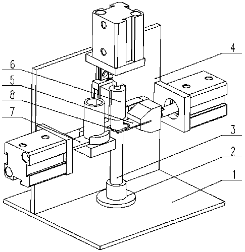
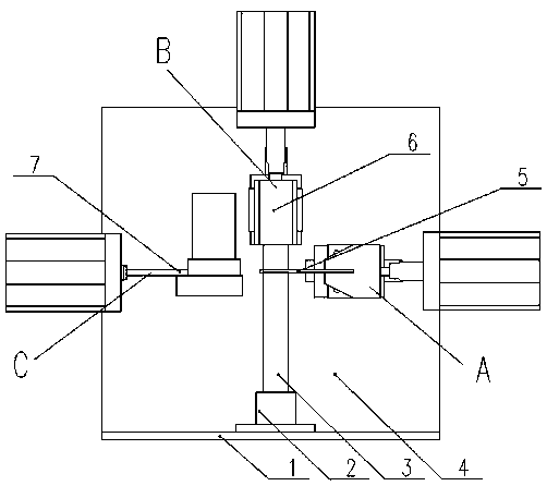
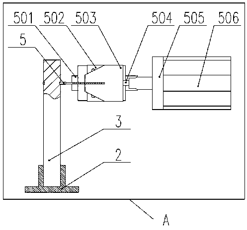
[0024] Such as figure 1 , figure 2 , image 3 , Figure 4 , Figure 5 , Image 6 , Figure 7 as well as Figure 8 As shown, an installation device for an open retaining ring with a detection function includes a base plate 1, a support seat 2, a rotating shaft 3, a spring groove 301, a side plate 4, a go-no-go gauge 5, a first guide rail 501, and a first slider 502 , clamping block 503, first cylinder connector 504, first cylinder fixing plate 505, first cylinder 506, hole clamping plate 507, shaft clamping plate 508, pressure head 6, second cylinder 601, second cylinder fixing Plate 602, second cylinder connector 603, second slider 604, second guide rail 605, push block 7, feeding barrel 701, pad 702, third cylinder fixing plate 703, third cylinder connector 704, third cylinder 705, the limit groove 706 and the opening retaining ring 8, the support base 2 is fixed on the base plate 1; the support base 2 is provided with a through hole, and the inside of the through hol...


PUM


Abstract

The invention provides a split washer mounting device with a detection function. The mounting device comprises a bottom plate, a supporting seat, a rotating shaft, a clamping spring groove, a side plate, a go and no-go gauge, a first guide rail, a first slide block, a clamping block, a first air cylinder connector, a first air cylinder fixing plate, a first air cylinder, a hole clamping plate, a shaft clamping plate, a pressing head, a second air cylinder, a second air cylinder fixing plate, a second air cylinder connector, a second sliding block, a second guide rail, a pushing block, a feeding barrel, a cushion block, a third air cylinder fixing plate, a third air cylinder connector, a third air cylinder, a limiting groove and a split washer. According to the split washer mounting devicewith the detection function, the split washer can be automatically assembled by means of the pushing block and other structures, the requirement for skills of operators is low, and the problem that the split washer is low in installation efficiency is solved; and in addition, the function of automatically detecting the bottom diameter of the clamping spring groove and the groove width of the clamping spring groove is further added, so that the phenomenon that the split washer falls off due to the facts that the bottom diameter of a clamping spring groove is large and the groove width of the clamping spring groove is small is effectively prevented and avoided.

Description

technical field [0001] The invention relates to the field of installing a retaining ring, in particular to a retaining ring installation device with a detection function. Background technique [0002] The shape of the open retaining ring is E-shaped, and it is usually used to limit the axial position of the bearing. The use of the open retaining ring is extremely wide, such as agriculture, industry, automobile industry, etc., as long as the bearing rotates, the retaining ring may be used. In the actual production process, it is usually used The snap ring pliers are used to install the snap ring. During the installation process, the requirements for the operator's job skills are high, the installation efficiency is low, and it is easy to cause the snap ring to fall off due to improper installation of the snap ring. Contents of the invention [0003] In view of the above problems, the present invention provides an installation device for an open retaining ring with a detecti...

Claims


Application Information

Patent Timeline
Patent Type & Authority Applications(China)
IPC IPC(8): B23P19/027
CPCB23P19/027
Inventor 张增良
Owner 嘉控电力股份有限公司
Why Eureka
Try Eureka