Automobile periphery non-blind area camera shooting and display system

A display system, no blind spot technology, applied in the field of vehicles, can solve problems such as accidents, accidents, and many traffic accidents

Inactive Publication Date: 2019-03-29
朱扩夫
View PDF5 Cites 0 Cited by
  • Summary
  • Abstract
  • Description
  • Claims
  • Application Information

AI Technical Summary

Problems solved by technology

[0002] The traditional car observes the surrounding road conditions on the left, right and rear through the left and right rearview mirrors and the rearview mirror above the driver's cab. Constantly turning left and right, sometimes taking care of the right, but not paying attention to the left, often causes accidents; the second is that there are blind spots for drivers to observe the surrounding road conditions, especially at the corners of the left and right front of large trucks. There is a blind spot, because the drivers in these two blind spots cannot observe, causing traffic accidents in particular; the third is that the traditional left and right rearview mirrors of automobiles all use curved glass reflectors, and the field of view is not wide. If the vehicle overtaking the vehicle does not reach a certain distance, the rearview mirror cannot detect it, and an accident will occur
It is known through the above disclosed technical content that three cameras are installed on the left side, the right side and the tail of the car, and the left rearview mirror and the right rearview mirror are used at the same time. Camera), while observing the left and right rearview mirrors, as well as the images from the left, right and rear cameras and the infrared rangefinder display, the line of sight workload is heavy, but the blind spots at the corners on both sides of the front of the car are still observed Less than the real situation, although the left and right rearview mirrors have added electric adjustment functions, but they are also affected by rain and limited by the arc field of view.

Method used


Image

  • Automobile periphery non-blind area camera shooting and display system
  • Automobile periphery non-blind area camera shooting and display system
  • Automobile periphery non-blind area camera shooting and display system

Examples


Embodiment Construction

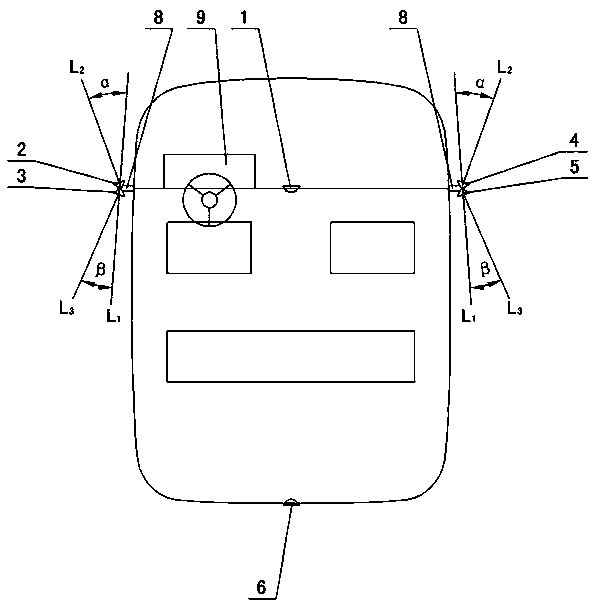
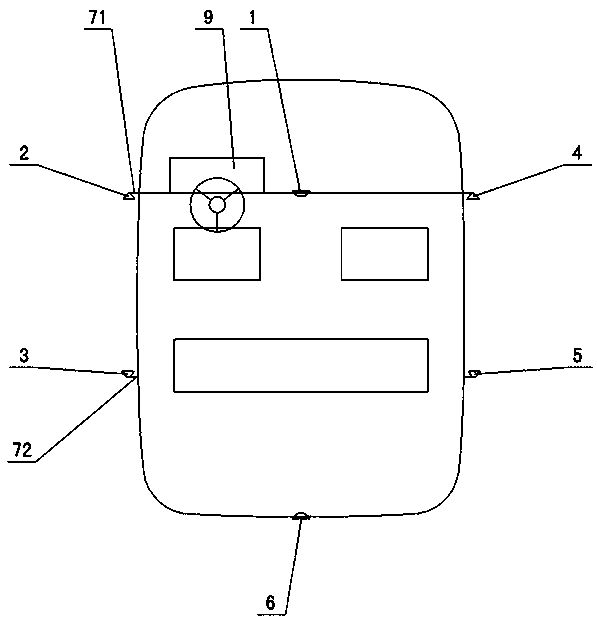
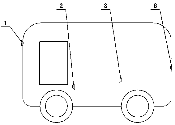
[0012] The invention relates to a camera and display system without blind spots around a car, such as figure 1 — Figure 5 As shown, it includes a camera, a display, and a controller, and is characterized in that: the camera includes a front camera 1, a left front camera 2 and a left rear camera 3 arranged on the left side of the car, and a left rear camera 3 arranged on the right side of the car. Right front camera 4 and right rear camera 5, rear camera 6 arranged at the rear of the car, a total of 6 cameras, 6 cameras are connected to the controller and display, said left front camera 2 and left rear camera 3 share a left support 7 or Two left supports. The left support is set on the door of the car cab or on the outer wall of the front of the car. The left support extends from the car shell by 50-200mm, and the parallel car shell is used as an installation line L 1 , The center line L of the setting angle of the left front camera 2 2 With installation line L 1 The included an...


PUM


Abstract

The invention relates to an automobile periphery non-blind area camera shooting and display system, which comprises a camera, a display and a controller, wherein the camera comprises a front camera, aleft front camera, a left rear camera, a right front camera, a right rear camera and a rear camera, the left front camera and the left rear camera share one or two left supports, taking a parallel car shell as a mounting line L1, an angle alpha between the setting angle central line L2 of the left front camera and the mounting line L1 equals to 15-60 degrees, an angle beta between the setting angle central line L3 of the left rear camera and the mounting line L1 equals to 10-60 degrees, if two left supports are arranged, the left rear support is arranged in the front, the left front support is arranged in the rear, one position is higher, the other position is lower, and the right front camera and the right rear camera share one or two right supports; the display is a liquid crystal display, and the liquid crystal display screen comprises a front camera plate, a left front camera plate, a left rear camera plate, a right front camera plate, a right rear camera plate and a rear camera plate.

Description

Technical field [0001] The present invention relates to a camera and display system installed on a car, in particular to a camera and display system with no blind spots (no blind spots) around the car. It is suitable for various fuel, gas, new energy and other vehicles, and is especially suitable for Large trucks, containers and other vehicles. Background technique [0002] Traditional cars observe the surrounding road conditions on the left, right, and rear through the left and right rearview mirrors and the rearview mirror above the cab. There are the following shortcomings: First, the driver’s head needs attention when driving. Constantly turning left and right, sometimes paying attention to the right, but not paying attention to the left, often causing accidents. Second, there are blind spots for drivers to observe the surrounding road conditions, especially at the front corners of the left and right fronts of large trucks. There is a blind spot. Drivers cannot observe these...

Claims


Application Information

Patent Timeline
Patent Type & Authority Applications(China)
IPC IPC(8): B60R1/00
CPCB60R1/00B60R2300/105B60R2300/8026
Inventor 朱扩夫朱彦忱
Owner 朱扩夫
Why Eureka
Try Eureka