Angle positioning device for distance-variable pull rod

A technology of angle positioning and variable pitch rods, which is applied in transportation and packaging, aircraft parts, propellers, etc. It can solve the problems of difficult installation of tooling, bumps, and difficulty in ensuring the angle of joint bearings at both ends, etc., to achieve easy operation and high angle accuracy Effect

Active Publication Date: 2019-03-29
CHINA HELICOPTER RES & DEV INST
View PDF6 Cites 5 Cited by
  • Summary
  • Abstract
  • Description
  • Claims
  • Application Information

AI Technical Summary

Problems solved by technology

[0004] Direct adjustment manually judges whether the planes of the joint bearings at both ends of the rod end are parallel to the lugs of their respective mounting lugs (moving ring lugs and variable pitch rocker lugs). This method is difficult to ensure the angle of the joint bearings at both ends, resulting in Collision between rod end joint bearing and mounting fork lug during helicopter flight
[0005] The existing tooling is adjusted by clamping block 8 to clamp the end face of the shank joint bearing at both ends of the pitch-variable pu

Method used


Image

  • Angle positioning device for distance-variable pull rod
  • Angle positioning device for distance-variable pull rod
  • Angle positioning device for distance-variable pull rod

Examples


Example Embodiment

[0030] In order to make the purpose, technical solutions and advantages of the implementation of this application clearer, the technical solutions in the implementation of the application will be described in more detail below in conjunction with the drawings in the implementation of the application. In the drawings, the same or similar reference numerals indicate the same or similar elements or elements with the same or similar functions. The described implementations are part of the implementations of the present application, rather than all of the implementations. The following embodiments described with reference to the drawings are exemplary, and are intended to explain the present application, but should not be understood as a limitation to the present application. Based on the implementation manners in this application, all other implementation manners obtained by those of ordinary skill in the art without creative work shall fall within the protection scope of this appl...


PUM


Abstract

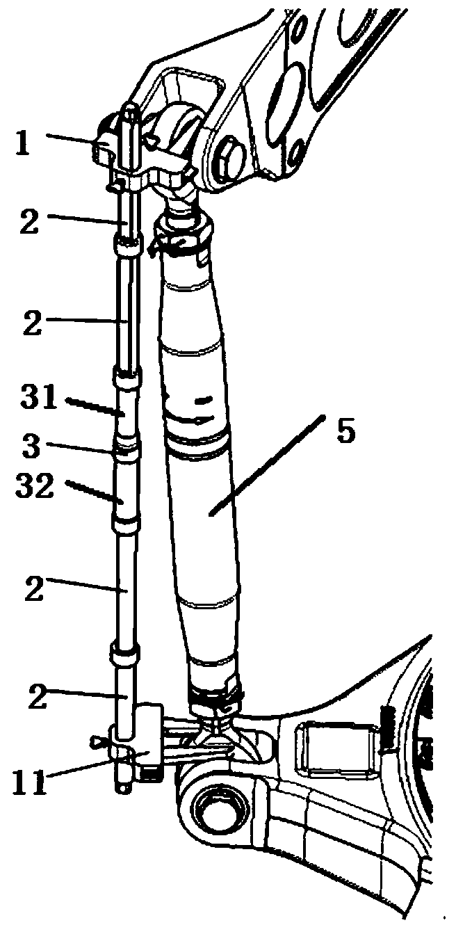
The invention provides an angle positioning device for a distance-variable pull rod and the angle positioning device comprises an angle adjusting rod (3), a locking mechanism and a clamp (1), whereinthe angle adjusting rod comprises a first rod (31) and a second rod (32) that are coaxial; and the end parts of the first rod (31) and the second rod (32) are rotationally connected; the locking mechanism is arranged at the joint of the first rod (31) and the second rod (32) and is used for fixing the first rod (31) and the second rod (32) after the first rod (31) and the second rod (32) rotate toa certain angle; The clamp (1) is arranged at the other ends of the first rod (31) and the second rod (32), and ear pieces at the two ends of the distance-variable pull rod are clamped by clamping part (11). According to the invention, joint bearings with handles at two ends of the distance-variable pull rod are clamped by the clamps at two ends, the relative angles of the joint bearings with handles at two ends of the distance-variable pull rod are directly ensured, so the angle positioning device has advantages of high angle precision, easy operation, suitability for different helicopters and like.

Description

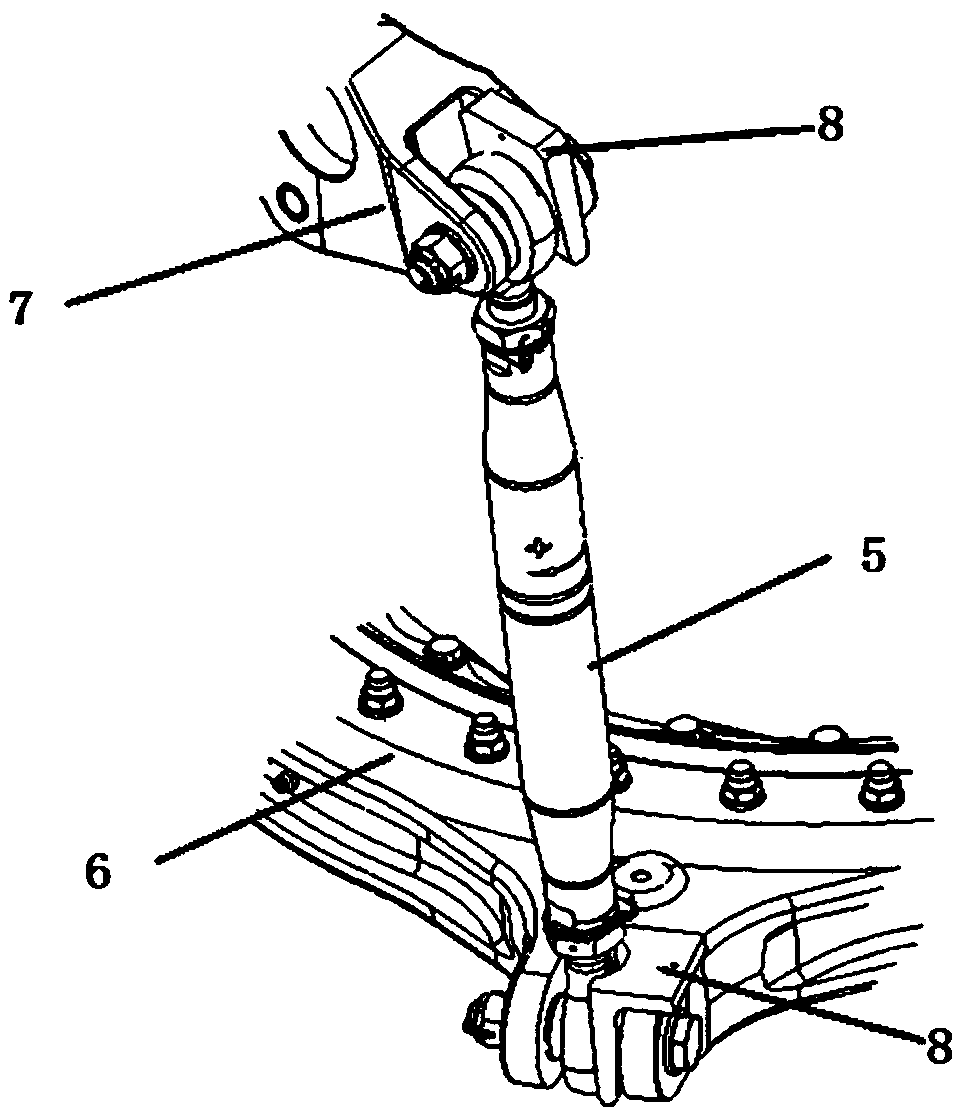
technical field [0001] The invention belongs to the technical field of helicopter rotor system design, and in particular relates to an angle positioning device for a pitch-variable pull rod. Background technique [0002] Such as figure 2 As shown, the pitch-changing tie rod 5 of the automatic tilter of the helicopter rotor system is connected with the 6 lugs of the moving ring and the 7 lugs of the pitch-changing rocker arm through bolts. Confirm the 7 fork lugs of the variable pitch rocker arm. Usually, after the large cone of the rotor adjusts the length of the pitch-variable tie rod 5, it is necessary to ensure that the planes of the joint bearings at both ends of the pitch-variable tie rod are parallel to their respective mounting lugs (moving ring lugs and pitch-variable rocker lugs) at the same time, indirectly ensuring that The relative angle of the shank spherical plain bearing at both ends. [0003] The length of the distance-variable tie rod has been basically d...

Claims


Application Information

Patent Timeline
IPC IPC(8): B64C11/32
CPCB64C11/32
Inventor 刘伟友范平平舒航杨广勇陆裕辉董锦山李永鑫
Owner CHINA HELICOPTER RES & DEV INST
Why Eureka
Try Eureka