Method for manufacture prism

A manufacturing method and prism technology, which are applied to prisms, manufacturing tools, and machine tools suitable for grinding workpiece planes, etc., can solve the problems of inclined sidewall errors, cutting errors, and cannot guarantee high-precision angular accuracy, and achieve high angular accuracy. Effect

Inactive Publication Date: 2006-12-06
FUJI PHOTO OPTICAL CO LTD
View PDF1 Cites 6 Cited by
  • Summary
  • Abstract
  • Description
  • Claims
  • Application Information

AI Technical Summary

Problems solved by technology

In addition, since the lamination and cutting of the plate glass and the split laminate are repeated, the cumulative error is further accumulated, and a cutting error also occurs during cutting, so the finally manufactured prism contains a very large error.
In addition, although the plate glass and the laminated divided body are arranged in a step-like shape along the inclined wall, cutting errors may occur during lamination or cutting, and there is a

Method used


Image

  • Method for manufacture prism
  • Method for manufacture prism
  • Method for manufacture prism

Examples


Embodiment Construction

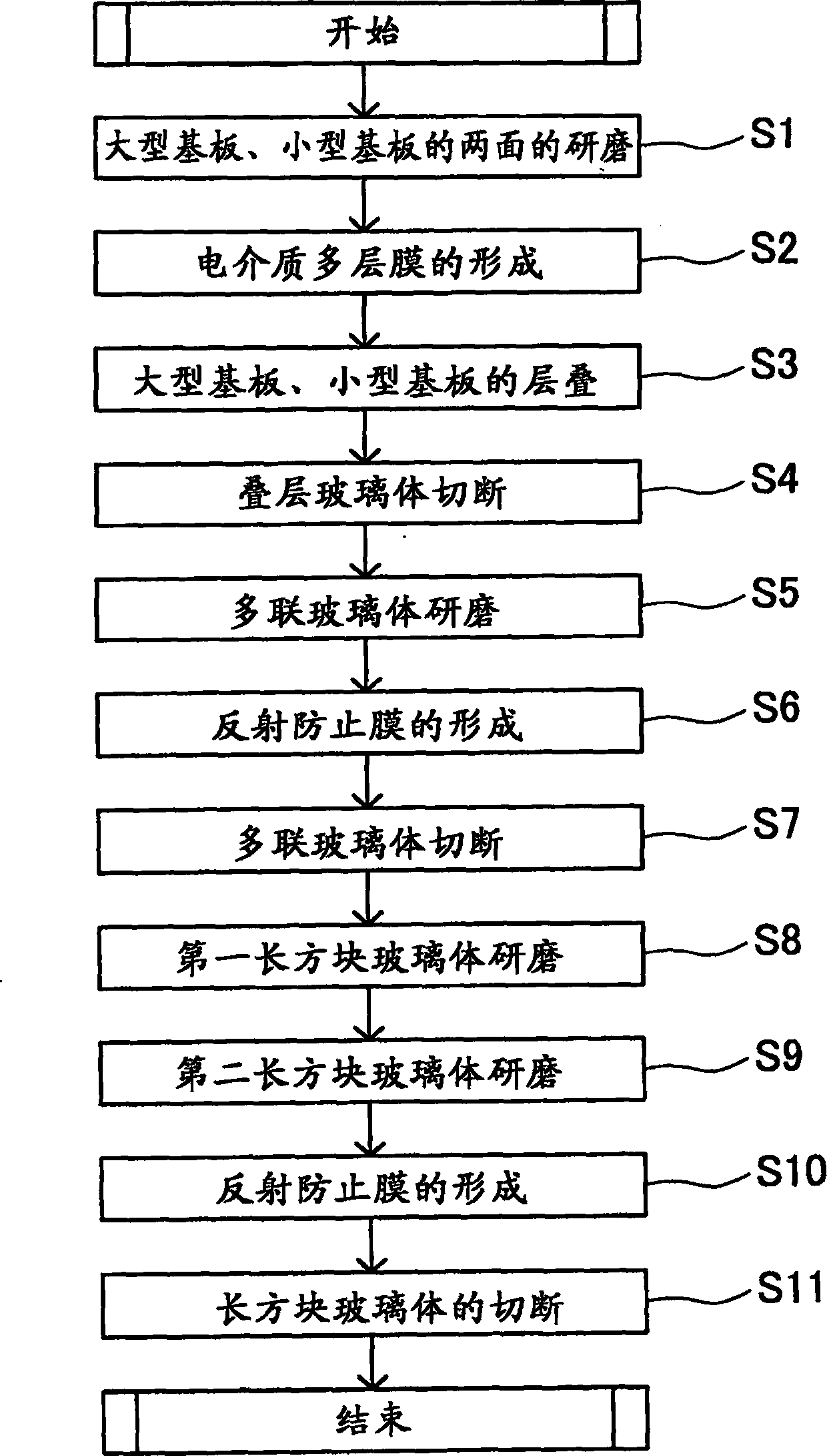
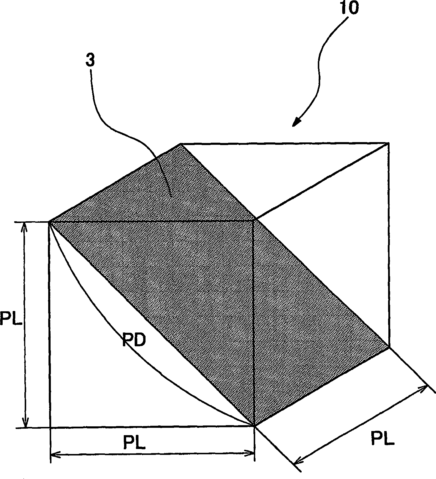
[0024] Below, according to figure 1 The flowchart of Figure 1 illustrates an embodiment of the invention. figure 2 It is the prism 10 finally manufactured. The prism 10 of this embodiment is a cubic optical element with one side PL long, and the dielectric multilayer film 3 is formed at an angle of 45° with respect to the optical axis. Here, in this embodiment, the diagonal length of each surface of the prism 10 (the long side of the surface on which the dielectric multilayer film 3 is formed) is defined as the diagonal length PD of the prism 10 (=PL×). In addition, an antireflection film having an antireflection function is formed on each surface of the prism 10 .

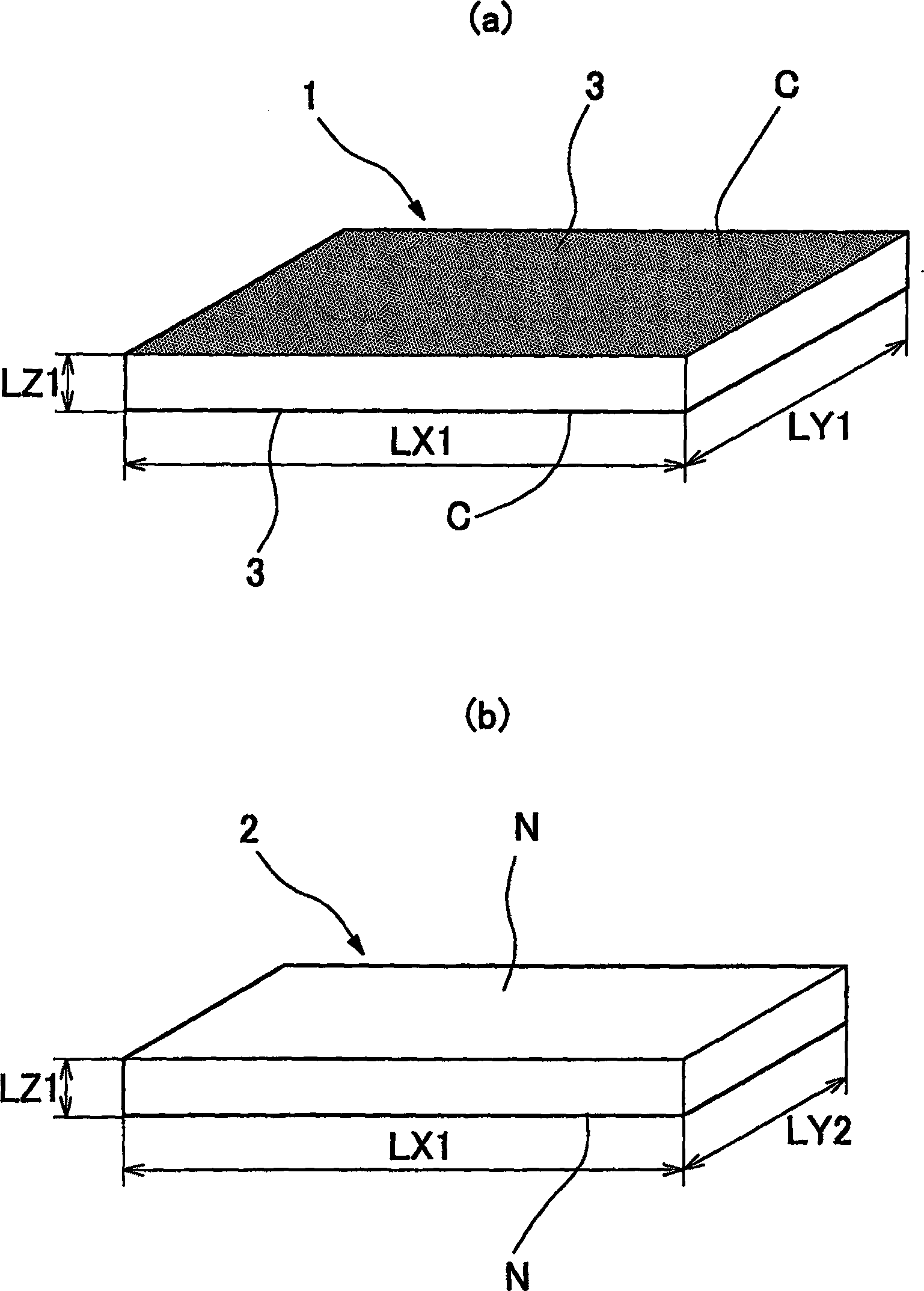
[0025] initially as image 3 As shown, a plurality of two types of flat substrates (substrates such as glass substrates) having different shapes are prepared. exist image 3 (a) shows a large substrate 1 having a long side (width) of LX1, a short side (depth) of LY1, and a thickness of LZ1. image 3 (b) sh...


PUM


Abstract

The invention relates to a method for preparing high-accuracy prism, comprising preparing large-scale base plate (1) and small-scale base plate, said large-scale base plate is platform, and the width and thickness of small-scale one is the same to that of large-scale, but the depth is smaller; forming dielectric multiple layer membrane (3) on one side of each base plate, laminating alternatively large-scale and small-scale base plate to form step in width direction according to thickness amount, shoeing out the two end of large-scale base plate in depth direction as base plate surface B; laminated vitreum (4) is cut along direction parallel to step, grinding cut surface of cut multigang vitreum (5); then, cutting multigang vitreum in vertical direction and getting rectangular vitreum (6); cutting it; grinding it taking showed base face B as guideline to form 45 degree grinding surface.

Description

technical field [0001] The invention relates to a method for manufacturing a prism. Background technique [0002] A component of an optical system typified by an optical pickup device includes, for example, a polarizing beam splitter. The polarizing beam splitter is an optical element that separates the laser light emitted from the light source into reflected light and transmitted light. Either one of the reflected light and the transmitted light is directed to the optical disc, and the other is directed to the APC for detecting the intensity of the laser light. (Automatic power control) by light components. Since the reflected light reflected by the polarizing beam splitter is generally reflected at an angle of 90°, the polarized light separation film constituting the polarizing beam splitter is arranged at an angle of 45° to the optical axis. Therefore, a cube-shaped prism was used as the polarization beam splitter, and the polarization separation film was formed on the ...

Claims


Application Information

Patent Timeline
IPC IPC(8): G02B5/04
CPCB24B7/24G02B1/11G02B5/04G02B5/30
Inventor 龙保民小野健治大塚寿关口隆史冈崎隆一
Owner FUJI PHOTO OPTICAL CO LTD
Why Eureka
Try Eureka