
System for illuminating an object

a technology of illuminating systems and objects, applied in the field of navigational engineering, can solve the problems of low reliability, low speed response of above-mentioned coordinators, and known systems that fail to provide high accuracy of measuring and achieve the effect of higher measuring accuracy of angular coordinates of targets

Inactive Publication Date: 2005-05-31
ALIEV ABDULLA SIRAZHUTDINOVICH +1
View PDF9 Cites 5 Cited by
  • Summary
  • Abstract
  • Description
  • Claims
  • Application Information

AI Technical Summary

Benefits of technology

[0014]The present invention has for its object to provide a system for lighting an object, said system ensuring a higher measuring accuracy of the angular coordinates of a target due to beam pointing at the center of the target image.

Problems solved by technology

Insofar as modulation of the radiant flux is performed mechanically with the aid of a modulating disk which is disposed in the focal plane of a lens and rotated by an electric motor at a constant speed, the known system fails to provide high accuracy of measuring angular coordinates of the target.
Mobile electromechanical clusters cause low reliability and low-speed response of the above-mentioned coordinators.
Besides, their construction does not allow directing mirror-reflected beams along their optic axes and, moreover, these target seekers are capable of tracing targets only within the immediate field of their vision and stop operating when the target is not seen, for they are not designed for operating in the search mode.
Yet, the known optoelectronic target seeker fails to point the beam at an object and seek for a target if the object is beyond its field of vision.

Method used


Image

  • System for illuminating an object
  • System for illuminating an object
  • System for illuminating an object

Examples


Embodiment Construction

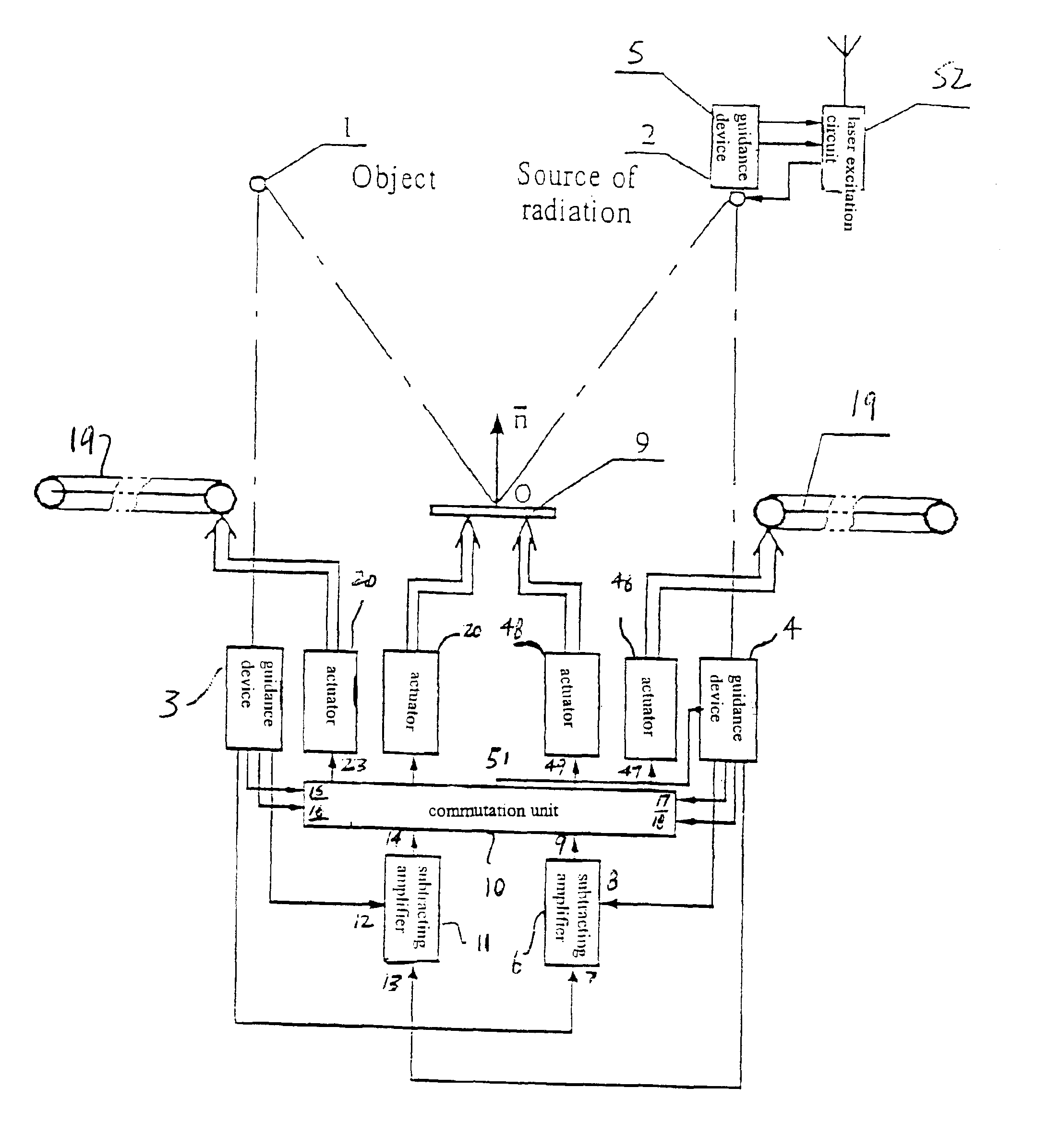
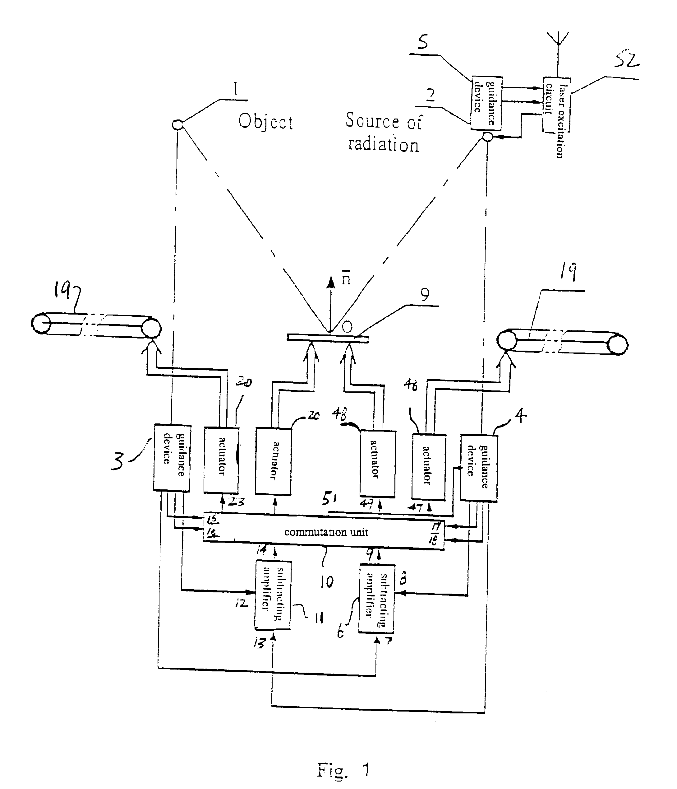
[0029]The system for lighting an object 1 (FIG. 1) comprises a radiation source 2 and guidance devices 3, 4, 5, of which the guidance device 3 is optically connected to the object 1, and the device 4, to the radiation source 2. The system further comprises a subtracting amplifier 6 having its inputs 7 and 8 connected to the respective outputs of the guidance devices 3 and 4, while the output thereof is connected to an input 9 of the commutation unit 10, and a subtracting amplifier 11 whose inputs 12 and 5 are connected to the outputs the guidance devices 3 and 4, respectively, and its output is connected to an input 14 of the commutation unit 10. Inputs 15 and 16 of the commutation unit 10 are connected to the corresponding outputs of the guidance device 3, while its inputs 17 and 18 thereof are connected to the respective outputs of the guidance device 4. In addition, the system comprises a mirror 19 with which kinematically coupled are actuators 20 having their inputs connected to...


PUM


Abstract

A system for lighting an object has a radiation source, a first guidance device optically connected to the object, a second guidance device and a first subtracting amplifier in communication with the first guidance device. The first subtracting amplifier has inputs and at least one output. A second subtracting amplifier is in communication with the first and second guidance devices. A commutation unit is in communication with the first and second guidance devices and the first and second subtracting amplifiers. First, second, third and fourth actuators are in communication with the commutation unit. A first mirror is in communication with and controlled by the first and second actuators and a second mirror is in communication with and controlled by the third and fourth actuators. The first and said second mirrors are controlled by the actuators so that the system can light an object by reflecting the radiation source.

Description

CROSS REFERENCE TO RELATED APPLICATIONS[0001]Applicants claim priority under 35 U.S.C. §119 of Russian Application No. 99111294 filed May 28, 1999. Applicants also claim priority under 35 U.S.C. §120 of PCT / RU00 / 00144 filed Apr. 21, 2000. The international application under PCT article 21(2) was not published in English.TECHNICAL FIELD[0002]The invention relates to navigational engineering, more specifically, to optoelectronic systems for autotracking of moving objects.BACKGROUND ART[0003]Known in the present state of the art are systems for automatic guidance and tracking of moving targets, which are based on the frequency, phase, pulse-height, time-pulse and amplitude-phase principles and can be used for illumination of objects (cf. L. Z. Kriksunov, I. F. Usoltsev. Infrared systems. Moscow, “Sovetskoye Radio” Publishing House, 1968, p.p. 157-239 (in Russian).[0004]Known coordinators (target seekers) generate signals, which are proportional to the constituents of the angle of misal...

Claims


Application Information

Patent Timeline
Patent Type & Authority Patents(United States)
IPC IPC(8): G01S17/66G01S17/00G01C21/24G01S3/784
CPCG01S17/66
Inventor ALIEV, ABDULLA SIRAZHUTDINOVICHAMIROV, SAID DZHAPAROVICH
Owner ALIEV ABDULLA SIRAZHUTDINOVICH
Learn More