Angular velocity measuring device and leg-moving robot

a technology of angular velocity and measuring device, which is applied in the direction of electric controllers, instruments, ignition automatic control, etc., can solve the problems of drifting from the actual angular velocity, and achieve the effect of increasing the accuracy of the estimated value of the posture angle and easy accumulation of errors

Inactive Publication Date: 2007-11-06
HONDA MOTOR CO LTD
View PDF41 Cites 5 Cited by
  • Summary
  • Abstract
  • Description
  • Claims
  • Application Information

AI Technical Summary

Benefits of technology

[0011]As described later, the predetermined time period is extremely short time (for example, a few milliseconds) and therefore the drift of the detected value generated within the predetermined time period is vanishingly low. Moreover, the term “drift” here indicates that the detected value of the angular velocity indicated by the detected output of the first sensor has a difference from a predetermined angular velocity (actual angular velocity) with time. If, for example, a vibratory gyroscope is used as a sensor for detecting the angular velocity, generally there is a need to remove low frequency components from the detected output of the vibratory gyroscope by means of the high-frequency pass filter in order to achieve precise measurement with the vibratory gyroscope. This is because of removing variation in the detected output during rest of the vibratory gyroscope, which has been caused by a mechanical effect resulting from a temperature change or the like. In general, the vibratory gyroscope does not generate a predetermined amount of detected output for a predetermined angular velocity, but generates a predetermined amount of detected output according to an angular velocity from the detected output during rest of the vibratory gyroscope.
[0014]According to this, the angular velocity measurement is obtained as one with the drift characteristic and the response characteristic of the detected outputs of the first sensor and the second sensor complementing each other. More specifically, the response of the measurement to the change in the actual angular velocity is substantially equivalent to that of the first sensor and the stability of the measurement in the state where the actual angular velocity is maintained virtually constant is substantially equivalent to that of the second sensor. Therefore, the angular velocity measurement has both the more preferable response of the first sensor and the more preferable stability of the second sensor, thereby achieving good response and stability. Moreover, the predetermined time period can be appropriately set and therefore the accuracy of the angular velocity measurement can be increased while maintaining good response of the angular velocity measurement when a change in the actual angular velocity is relatively rapid.
[0016]More specifically, the detected output of the vibratory gyroscope is high in response to a change in the angular velocity and the detected output of the gas rate gyroscope is high in stability when the angular velocity is virtually constant. Therefore, with the use of the vibratory gyroscope and the gas rate gyroscope as the first sensor and the second sensor, respectively, both the response and the stability of the angular velocity measuring device according to the present invention can be preferably increased. Moreover, with the use of the vibratory gyroscope and the gas rate gyroscope low in price, generally very precise angular velocity measuring device can be provided at a low price.
[0018]According to the leg-moving robot, the posture angle estimation means estimates the posture angle of the predetermined portion of the robot at least on the basis of the angular velocity measurement obtained by the angular velocity measuring device, and therefore the posture angle of the predetermined portion can be accurately estimated independently of the motion velocity of the predetermined portion. Therefore, by generating the joint drive command signal of the robot at least on the basis of the posture angle and activating the joint actuator of the robot according to the joint drive command signal, the posture of the robot can be appropriately controlled to a desired position, independently of whether the movement of the robot is rapid or slow.
[0021]More specifically, although the posture angle of the predetermined portion can be estimated by integrating the angular velocity measurements obtained by the angular velocity measuring device, errors are easily accumulated in the integral of the angular velocity measurements. Therefore, the acceleration sensor is provided in addition to the angular velocity measuring device to estimate the posture angle of the predetermined portion on the basis of the measurements. This enables the accuracy of the estimated value of the posture angle to be increased.

Problems solved by technology

If the low frequency components are removed from the detected output of the first sensor, the detected output corresponding to the angular velocity of the low frequency or a certain angular velocity cannot be obtained, thereby causing drift from the actual angular velocity.

Method used


Image

  • Angular velocity measuring device and leg-moving robot
  • Angular velocity measuring device and leg-moving robot
  • Angular velocity measuring device and leg-moving robot

Examples


Embodiment Construction

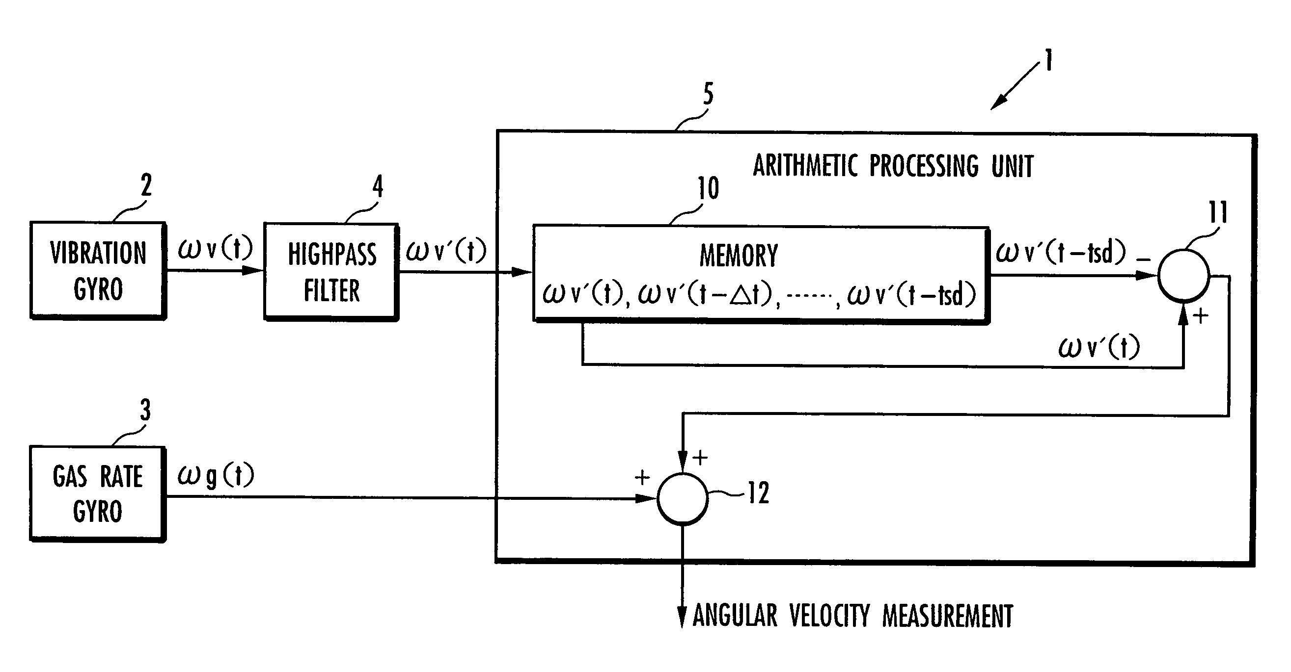
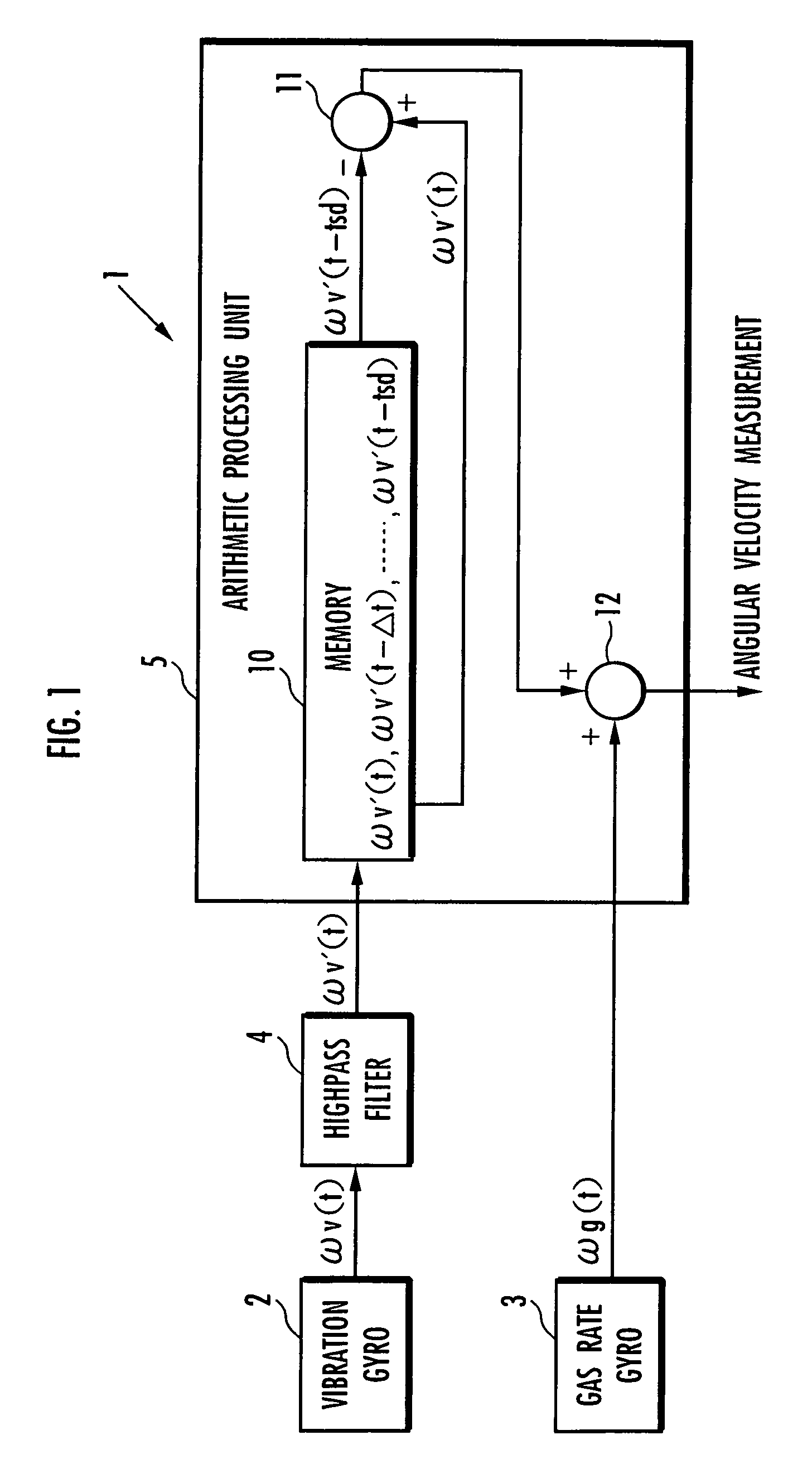
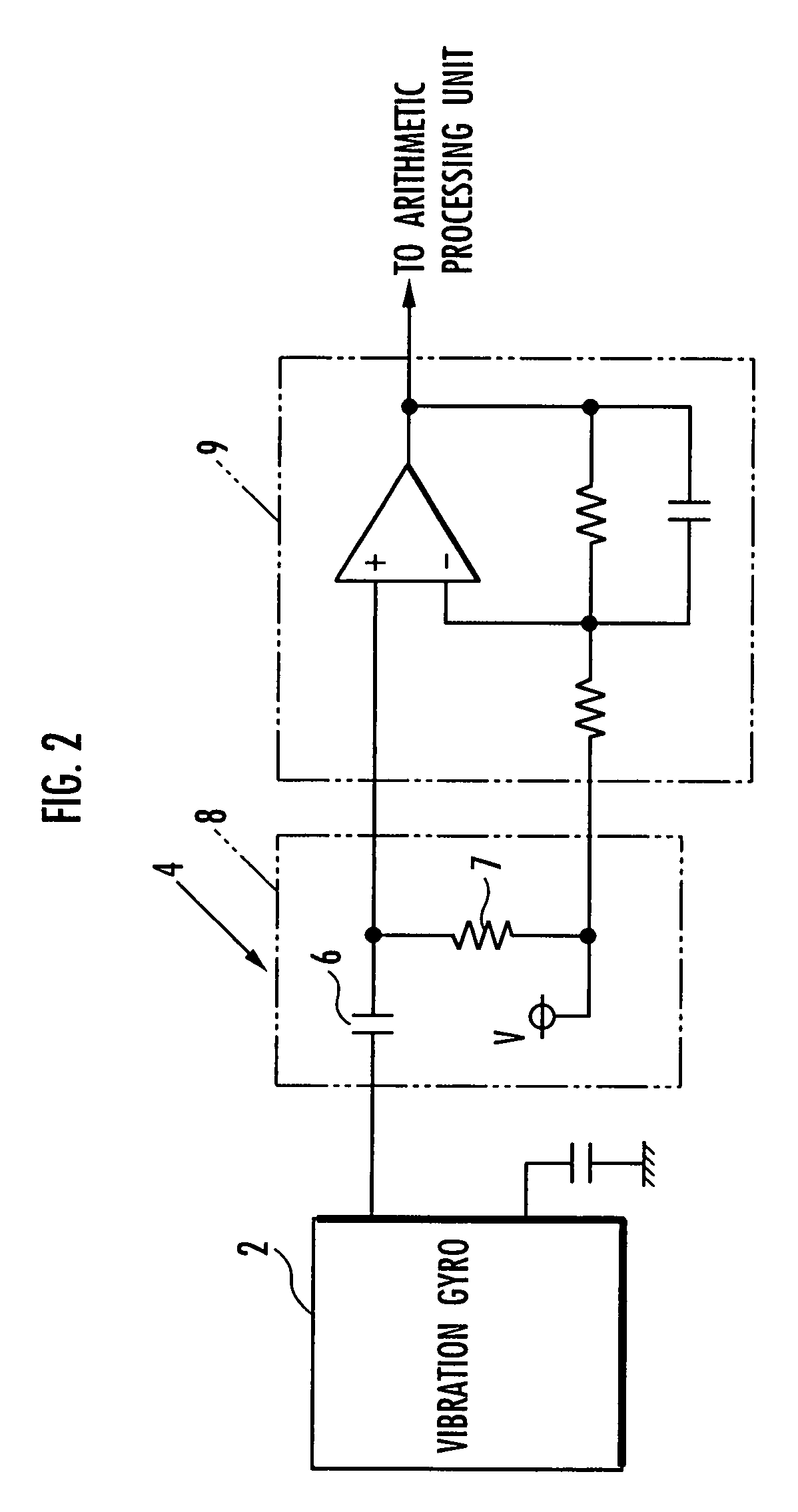
[0030]An embodiment of an angular velocity measuring device according to the present invention will be described below with reference to FIG. 1 to FIG. 5. FIG. 1 is a block diagram showing a configuration of an angular velocity measuring device according to this embodiment; FIG. 2 is a circuit diagram showing a concrete circuit configuration between a vibratory gyroscope 2 and an arithmetic processing unit 5 shown in FIG. 1; FIG. 3 is a graph showing an output characteristic of the vibratory gyroscope; FIG. 4 is a graph showing an output characteristic of a gas rate gyroscope; and FIG. 5 is a graph showing an output characteristic of the angular velocity measuring device shown in FIG. 1.

[0031]Referring to FIG. 1, an angular velocity measuring device 1 of this embodiment includes a vibratory gyroscope 2 as a first sensor, a gas rate gyroscope 3 as a second sensor, a highpass filter 4 (high-frequency pass filter) that receives a detected output ωv of the vibratory gyroscope 2, and an ...


PUM


Abstract

An angular velocity measuring device (1) includes a first sensor (2) (vibration gyro) and a second sensor (3) (gas rate gyro). The detection output of the first sensor (2) is inputted to a high pass filter (4). Output of the filter (4) is stored and held in time series in a memory (10). Subtraction processing means (11) successively executes processing of subtracting the output of the filter (4) ωv′(t−tsd) before a predetermined time tsd from the output of the filter (4) ωv′(1). The value thus obtained is successively added to the output of the second sensor (3) ωg(t) by addition processing means (12) so as to obtain the measurement value of the angular velocity. Thus, it is possible to provide an angular velocity measuring device capable of giving an angular velocity measurement value having a high response and stability at a reasonable cost.

Description

CROSS-REFERENCE TO RELATED APPLICATION[0001]This application is a National Stage entry of International Application No. PCT / JP2005 / 012948, filed Jul. 13, 2005, the entire specification claims and drawings of which are incorporated herewith by reference.FIELD OF THE INVENTION[0002]The present invention relates to an angular velocity measuring device and a leg-moving robot.BACKGROUND ART[0003]As sensors (rate gyroscopes) for detecting angular velocities, a vibratory gyroscope, a gas rate gyroscope, and the like are well-known. Moreover, for example, as described in Japanese Laid-Open Patent Publication No. 2000-66722 (hereinafter, referred to as patent document 1), there is a known technology in which a movable body is provided therein with a high-sensitivity gyroscope sensor having a relatively narrow detectable angular velocity range and a low-sensitivity gyroscope sensor having a relatively wide detectable angular velocity range, so as to allow selective switching between the low-s...

Claims


Application Information

Patent Timeline
Patent Type & Authority Patents(United States)
IPC IPC(8): B25J5/00G01C19/00G01P9/00B25J13/08B25J19/02G01C19/56G01C19/5776
CPCB25J13/088G01P9/00G01C19/56G01C19/5776G01C19/005
Inventor SAOTOME, KOUJIOKAMOTO, NORIAKIHIRAYAMA, SHINYUSAKOGOSHI, TOMOHIROSHIMADA, YOICHIAKAHORI, SHIGETOHORI, KENGOSAIKA, HITOSHI
Owner HONDA MOTOR CO LTD
Why Eureka
Try Eureka