
Conveying chain shifting mechanism

A conveyor chain and chain link technology, applied in the field of logistics transportation equipment, can solve the problems of large space occupation, high production cost, easy to touch the surrounding parts, etc., to achieve the effect of reducing quantity, saving cost, and facilitating direct modification

Pending Publication Date: 2019-03-29
嘉善县奔达链条厂
View PDF10 Cites 0 Cited by
  • Summary
  • Abstract
  • Description
  • Claims
  • Application Information

AI Technical Summary

Problems solved by technology

[0002] The commonly used conveyor chain dialing mechanism uses plastic and other materials to make the mounting seat. In order to ensure the structural strength, its volume is generally large, and the lever is placed on the side of the mounting seat, which takes up a lot of space and is easy to touch the surrounding parts when moving. If there is a fault, the mounting seat needs to be molded separately. When it is damaged, specific parts need to be replaced, and the mounting seat is integrated with the chain link of the conveyor chain. When replacing, the chain link needs to be replaced together, and the production cost is high.

Method used


Image

  • Conveying chain shifting mechanism
  • Conveying chain shifting mechanism
  • Conveying chain shifting mechanism

Examples


Embodiment Construction

[0021] In order to make the technical means, creative features, goals and effects achieved by the present invention easy to understand, the present invention will be further elaborated below in conjunction with illustrations and specific embodiments.

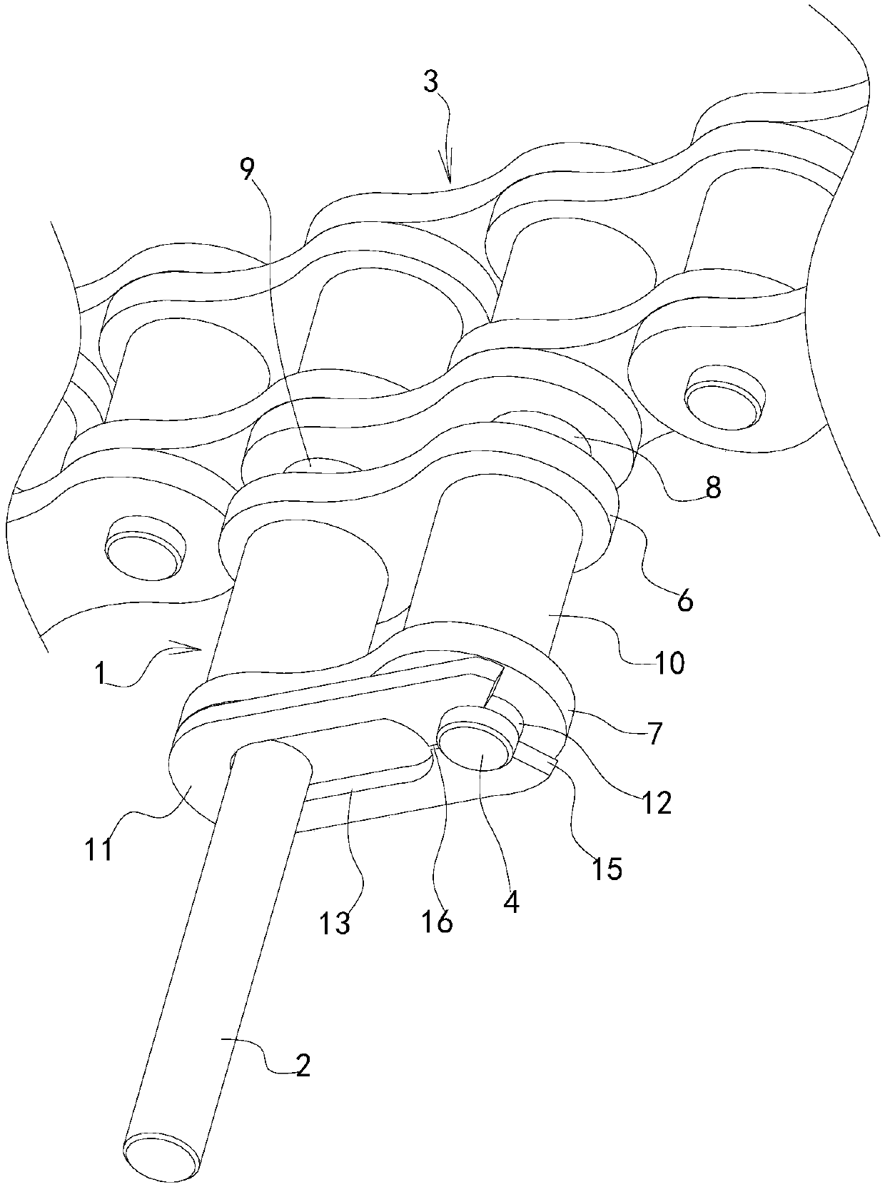
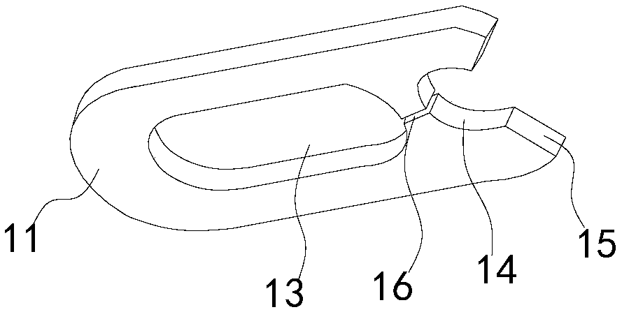
[0022] Such as figure 1 , figure 2 , image 3 As shown, the conveyor chain dialing mechanism proposed by the present invention includes a mounting base 1 and a driving lever 2. The driving lever is assembled on the mounting base, and the mounting base is assembled on the chain link 3 of the conveyor chain through a joint structure. When the conveyor chain is running, it is installed The seat and the driving rod move together with the chain link, and the workpiece is moved and conveyed by the driving rod. The joint structure includes the connecting pin 4 and the positioning pin 5 on the chain link, the connecting hole and the positioning hole in the mounting seat, and the connecting pin. The outer section extends into the conn...


PUM


Abstract

The invention provides a conveying chain shifting mechanism. The conveying chain shifting mechanism comprises a mounting base and a shifting lever, wherein the shifting lever is assembled on the mounting base, the mounting base is assembled on a chain link of a conveying chain through a junction structure, the junction structure comprises a connecting pin, a locating pin, a connecting hole and a locating hole, wherein the connecting pin and the locating pin are located on the chain link, the connecting hole and the locating hole are located in the mounting base, the outer side section of the connecting pin extends into the connecting hole, the outer side section of the positioning pin is inserted into the positioning hole, the mounting base comprises an inner base piece and an outer base piece, inner connecting holes are formed in the two ends of the inner base piece correspondingly, the two ends of the outer base piece are correspondingly provided with outer connecting holes, a firstsleeve and a second sleeve are arranged between the inner connecting holes and the outer connecting holes which are corresponding in position correspondingly, the two ends of the first sleeve and thetwo ends of the second sleeve are correspondingly embedded in the inner connecting holes and the outer connecting holes, an inner hole of the first sleeve serves as the connecting hole, and an inner hole of the second sleeve serves as the positioning hole. According to the conveying chain shifting mechanism, the structure of the mounting base is basically consistent with the structure of the chainjoint so that the cost can be saved, rapid assembly and disassembly can be achieved, the maintenance is convenient, and the working efficiency can be improved.

Description

technical field [0001] The invention relates to logistics conveying equipment, in particular to a dial-type conveying chain. Background technique [0002] The commonly used conveyor chain dialing mechanism uses plastic and other materials to make the mounting seat. In order to ensure the structural strength, its volume is generally large, and the lever is placed on the side of the mounting seat, which takes up a lot of space and is easy to touch the surrounding parts when moving. If a fault occurs, the mounting seat needs to be molded separately. When it is damaged, specific parts need to be replaced, and the mounting seat is integrated with the chain links of the conveyor chain. When replacing, the chain links need to be replaced together, and the production cost is high. Therefore, it is necessary to optimize the structure of this conveyor chain to overcome the above-mentioned defects. Contents of the invention [0003] The purpose of the present invention is to provide...

Claims


Application Information

Patent Timeline
Patent Type & Authority Applications(China)
IPC IPC(8): B65G17/38
CPCB65G17/38
Inventor 杨易
Owner 嘉善县奔达链条厂
Features
  • Generate Ideas
  • Intellectual Property
  • Life Sciences
  • Materials
  • Tech Scout
  • Unparalleled Data Quality
  • Higher Quality Content
  • 60% Fewer Hallucinations
Learn More