Intelligent feeding and discharging system with accurate positioning function for circuit board electroplating line

A technology for precise positioning and circuit boards, applied in the direction of electrolysis, electrolysis components, cells, etc., can solve the problems that the electroplating clamp cannot clamp the circuit board, affect the quality of circuit board plating, and the high rate of circuit board dropouts, etc., to reduce time, Effect of reducing impact and reducing board drop rate

Inactive Publication Date: 2019-03-29
佛山市阳和智能科技有限公司
View PDF0 Cites 4 Cited by
  • Summary
  • Abstract
  • Description
  • Claims
  • Application Information

AI Technical Summary

Problems solved by technology

However, the suction cup absorbs the middle position of the circuit board and contacts the circuit board, which easily deforms the circuit board and affects the plating quality of the circuit board
[0005] Moreover, in the step of robot loading and unloading, the position set by the robot is fixed, and the electroplating flybar will be deformed during the process of hoisting and electroplating. Among them, the electroplating flybar is electroplating in the electroplating pool Due to the shaking of the electroplating solution and the deformation of the force, the position of the electroplating clips on the electroplating flybar will shift. These shifts are random and non-directional, and even the two electroplating clips holding the same circuit board are dislocated up and down. In the case that the line connecting the clamping points of the two electroplating clips forms an angle with the horizontal plane, since the circuit board is placed horizontally on the electroplating flybar for clamping, at this time, one of the electroplating clips will not be able to clamp the circuit. In the case of the edge of the board, the drop rate of the circuit board is still high

Method used


Image

  • Intelligent feeding and discharging system with accurate positioning function for circuit board electroplating line
  • Intelligent feeding and discharging system with accurate positioning function for circuit board electroplating line
  • Intelligent feeding and discharging system with accurate positioning function for circuit board electroplating line

Examples


Embodiment Construction

[0037] In the following, the present invention will be further described in conjunction with the accompanying drawings and specific embodiments, so as to understand more clearly the technical idea claimed in the present invention. It is only stated here that the words for directions such as up, down, left, right, front, back, inside, and outside that appear or will appear in the text of the present invention are only based on the accompanying drawings of the present invention, and are not specific to the present invention. limited.

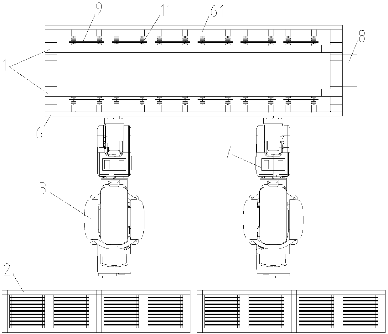
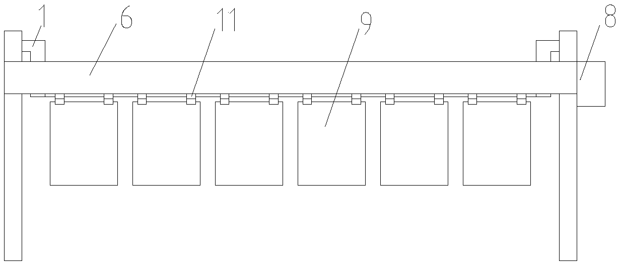
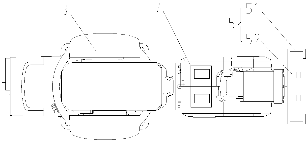
[0038] like Figure 1-7 As shown, the present invention discloses an intelligent loading and unloading system for a circuit board electroplating line that can be precisely positioned, including an electroplating flying bus 1, a board loading and unloading robot 3, a master controller 4, and a material frame 2 for placing circuit boards. Among them, the upper and lower plate robot 3 preferably adopts a six-axis robot. The six-axis robot is driven ...


PUM


Abstract

The invention relates to the technical field of circuit board electroplating, in particular to an intelligent feeding and discharging system with an accurate positioning function for a circuit board electroplating line. The system comprises electroplating bars, a board feeding and discharging robot, a main controller and a material frame used for placing circuit boards; number of the electroplating bars are provided with a plurality of electroplating clamps along the length direction of the electroplating bars, the board feeding and discharging robot is used for moving the circuit boards between the material frame and the electroplating clamps in a reciprocating mode, and a clamping device and a visual detection device are arranged at the execution tail end of the board feeding and discharging robot, and the clamping device is used for clamping the edges of the circuit boards; when the boards are fed and discharged, the visual detection device is used for photographing the electroplating clamps and the circuit boards on the electroplating clamp correspondingly, and the photographing data is sent to a master controller, the main controller controls the board feeding and dischargingrobots to work to enable the clamping device to transfer the circuit boards to corresponding board feeding and discharging positions. The board feeding and discharging system of the circuit board canaccurately realize the feeding and discharging of the circuit boards.

Description

technical field [0001] The invention relates to the field of circuit board electroplating technology, in particular to an intelligent upper and lower board system for a circuit board electroplating line that can be precisely positioned. Background technique [0002] The electroplating flybar is an important part of the circuit board electroplating line. Its function is to fix the circuit board and transfer the circuit board to different electroplating pools for electroplating. The upper and lower plates are important processes in the electroplating production steps of the circuit board. [0003] Most of the traditional circuit board electroplating lines adopt the method of manual loading and unloading, that is, manually move the unplated circuit board to the electroplating clip on the electroplating flybar for clamping or manually put the electroplating clip on the electroplating flybar to complete the electroplating line Take it off, the work efficiency is low. The four si...

Claims


Application Information

Patent Timeline
Patent Type & Authority Applications(China)
IPC IPC(8): C25D7/00C25D17/06C25D21/12C25D17/00
CPCC25D7/00C25D17/00C25D17/06C25D21/12
Inventor 刘振锋
Owner 佛山市阳和智能科技有限公司
Why Eureka
Try Eureka