Automatic curtain hanging hook
A curtain, automatic technology, applied in the direction of windows/doors, door/window protection devices, shading screens, etc., can solve the problem of not having the function of self-installation
- Summary
- Abstract
- Description
- Claims
- Application Information
AI Technical Summary
Problems solved by technology
Method used
Image

Examples
Embodiment 1
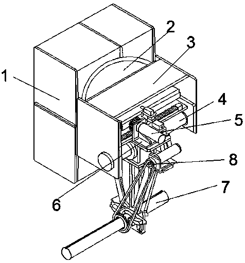
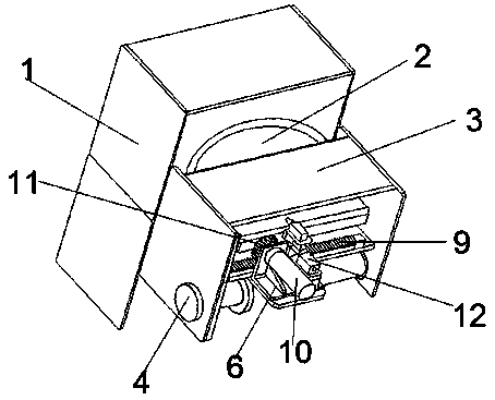
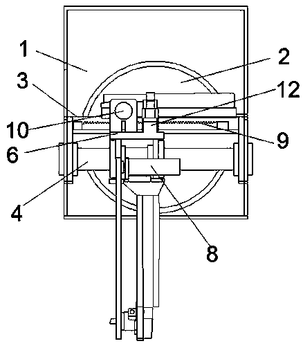
[0029] Embodiment 1: refer to Figure 1-3, an automatic curtain hook, comprising a rotating disk 2 and a fixed shell 3, and also includes an automatic holder 1, a moving device 5 and a rotating device 8; the rotating disk 2 is fixedly installed on the outer surface of the automatic holder 1, and the rotating disk 2 The outer surface is fixedly connected with the fixed shell 3, and the movable rod 4 is installed in the fixed shell 3 and the movable rod 4 runs through the left and right sides of the fixed shell 3. There is a fixed platform 6, the bottom of the fixed platform 6 is fixedly connected with the upper end of the rotating device 8, the bottom of the rotating device 8 is movably sleeved with a movable shaft 7, the moving device 5 includes a moving rotating shaft 10 and a moving motor 12, and the inner lateral direction of the fixed casing 3 An engagement groove 9 is provided, and the inner end of the moving shaft 10 is fixedly connected with a clamping gear 11, and the ...
Embodiment 2
[0031] Embodiment 2: refer to Figure 4-6 , the difference in connection with the basis of Embodiment 1 is that the automatic fixer 1 includes a protective case 13, a fixed motor 16 and a fixed rivet 17, the rotating disc 2 is fixedly installed on the outer surface of the protective case 13, and the inner center of the protective case 13 Part of the vertical fixed installation is a moving rail 14, a connecting plate 15 is movably socketed on the moving rail 14, and a fixed rivet 17 is movably installed at the bottom of the connecting plate 15 away from the center. One-to-one correspondence with the fixed rivets 17, the fixed motor 16 is fixedly installed at the center of the upper surface of the connecting plate 15, the output shaft of the fixed motor 16 is fixedly equipped with a driving gear 18, and the connecting plate 15 is movably equipped with a driven gear set 19 and The middle part of the driven gear set 19 runs through the connecting plate 15, and the outer side of th...
Embodiment 3
[0034] Embodiment 3: refer to Figure 7-10 , the difference in connection with the basis of Embodiment 1 is that the rotating device 8 includes a rotating motor 31, a fixed mount 32 and a rotating gear 34, the upper end of the fixed mount 32 is fixedly connected with the bottom surface of the fixed table 6, and the rotating gear 34 movable sleeve Connected to the bottom of the fixed frame 32, the rotating motor 31 is fixedly installed on the upper surface of the fixed table 6, the output shaft of the rotating motor 31 is fixedly equipped with a running wheel, and the outer ring of the rotating wheel is movably connected with a belt 33, and the other side of the belt 33 It is movably connected with the outer ring of the rotating gear 34 .
[0035] A slide block 35 is fixedly installed on the inner ring of the rotating gear 34 , and a fixed groove 36 is arranged on the movable shaft 7 , and the slide block 35 matches the fixed groove 36 .
[0036] The automatic curtain hook, by...
PUM
 Abstract
Description
Claims
Application Information
 - R&D
- Intellectual Property
- Life Sciences
- Materials
- Tech Scout
- Unparalleled Data Quality
- Higher Quality Content
- 60% Fewer Hallucinations
Browse by: Latest US Patents, China's latest patents, Technical Efficacy Thesaurus, Application Domain, Technology Topic, Popular Technical Reports.
© 2025 PatSnap. All rights reserved.Legal|Privacy policy|Modern Slavery Act Transparency Statement|Sitemap|About US| Contact US: help@patsnap.com