Engine crankshaft signal disc abrasion detection method and device and electronic control unit

A signal plate and engine technology, applied to engine components, machines/engines, mechanical equipment, etc., can solve problems such as unstable engine speed, traveling car, and no synchronous signal of the engine

Inactive Publication Date: 2019-03-29
WEICHAI POWER CO LTD
View PDF6 Cites 4 Cited by
  • Summary
  • Abstract
  • Description
  • Claims
  • Application Information

AI Technical Summary

Benefits of technology

This patented technology helps prevent damage caused by excessive use or abrasion from affecting the performance of an internal combustion engine's components such as its pistons. It uses signals made up of teeth arranged along their edges instead of just one single point like other parts of the mechanism. By comparing these measurements against predeteriorating standards, we are able to identify when there may be any signs of dirt buildup within them.

Problems solved by technology

The technical problem addressed in this patented solution for detecting when an engine's cranking system needs maintenance due to damage caused by wearing out its components like gears during operation.

Method used


Image

  • Engine crankshaft signal disc abrasion detection method and device and electronic control unit
  • Engine crankshaft signal disc abrasion detection method and device and electronic control unit
  • Engine crankshaft signal disc abrasion detection method and device and electronic control unit

Examples


Embodiment 1

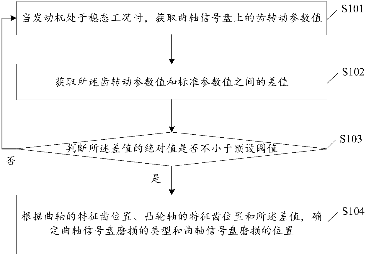
[0066] see figure 1 , which is a flow chart of an implementation of a method for detecting wear of an engine crankshaft signal disc provided in an embodiment of the present application.

[0067] The detection method of the engine crankshaft signal plate wear provided by the embodiment of the present application includes:

[0068] S101: When the engine is in a steady state condition, obtain the tooth rotation parameter value on the crankshaft signal plate.

[0069] Steady state condition means that the engine is in a steady state. Whether the engine is in a steady-state condition can be determined based on various engine parameters.

[0070] As an example, whether the engine is in a steady-state operating condition may be determined according to whether the rotational speed of the engine is stable. If the rotational speed of the engine is stable, it means that the engine is in a steady state; if the rotational speed of the engine is unstable, it means that the engine is not ...

Embodiment 2

[0138] Embodiment 2 is an improvement made on the basis of Embodiment 1. For the sake of brevity, the parts of Embodiment 2 and Embodiment 1 that have the same content will not be repeated here.

[0139] see Figure 5 , which is a flow chart of another implementation of the method for detecting the wear of the engine crankshaft signal disc provided in the embodiment of the present application.

[0140] The detection method of the engine crankshaft signal plate wear provided by the embodiment of the present application includes:

[0141] S201: Determine whether the engine is in a steady state. If yes, execute S202; if not, execute S201.

[0142] If the engine is not in a steady state condition, the obtained crankshaft signal plate tooth rotation parameter value is inaccurate, reducing the accuracy of determining the type of crankshaft signal plate wear and the location of the crankshaft signal plate wear. Thus, to improve the accuracy of determining the type of crankshaft si...

Embodiment approach

[0174] As another implementation, the tooth rotation parameter value is the number of tooth periods; the tooth period is the time interval between two adjacent teeth on the crankshaft signal plate;

[0175] The first determination module 604 specifically includes:

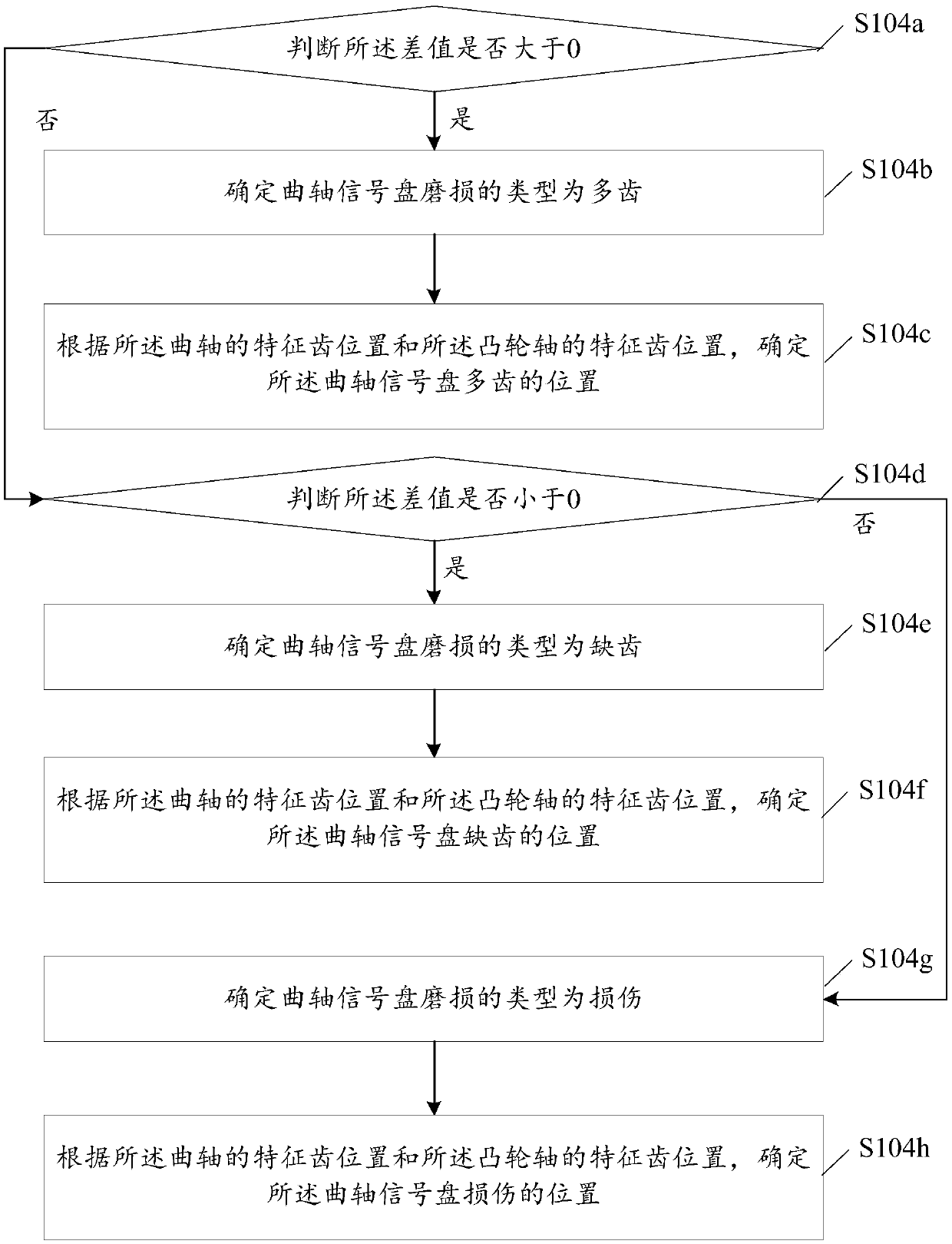
[0176] The second judging submodule is used to judge whether the difference is greater than 0;

[0177] The third determining submodule is used to determine that the type of crankshaft signal disc wear is multi-tooth if the difference is greater than 0, and determine the The multi-tooth position of the crankshaft signal plate;

[0178] The fourth determining submodule is used to determine that the type of crankshaft signal plate wear is missing teeth if the difference is less than 0, and determine the The location of the missing tooth on the crankshaft signal plate.

[0179] As yet another implementation, the value of the tooth rotation parameter is the circumference of the tooth; wherein, the circumference of t...


PUM


Abstract

The invention discloses an engine crankshaft signal disc abrasion detection method and device and an electronic control unit. According to the engine crankshaft signal disc abrasion detection method,whether the crankshaft signal disc is worn or not can be determined according to the difference value between the tooth rotation parameter value and the standard parameter value, and if the absolute value of the difference value is not smaller than a preset threshold value, determining that the crankshaft signal disc is abraded; in addition, according to the characteristic tooth position of the crankshaft, the characteristic tooth position of the cam shaft and the difference value, and determining the abrasion type of the crankshaft signal disc and the position of the abrasion of the crankshaft signal disc. According to the engine crankshaft signal disc abrasion detection method, whether the crankshaft signal disk is worn or not can be determined, the abrasion type of the crankshaft signaldisc and the abrasion position of the crankshaft signal disc can be determined, and the abrasion of the crankshaft signal disc can be rapidly processed.

Description


Claims


Application Information

Patent Timeline
Owner WEICHAI POWER CO LTD
Why Eureka
Try Eureka