Quick installation device for self-locking inward inclined type strain sensor

A technology of strain sensor and installation device, applied in the direction of measurement device, mechanical device, mechanical measurement device, etc., can solve the problems of easily damaged sensor, nut consumption, improper operation, etc., to ensure measurement accuracy and work efficiency, improve effective performance and accuracy, avoid unusable effects

Pending Publication Date: 2019-03-29
TONGJI UNIV
View PDF0 Cites 0 Cited by
  • Summary
  • Abstract
  • Description
  • Claims
  • Application Information

AI Technical Summary

Problems solved by technology

[0004] Although the above strain sensor fixing method can effectively fix the sensor, the disadvantages are also obvious: the separation design of the nut and the nut makes losing one of them means losing the functionality of the whole device; etc.), tightening the nut at this position is more labor-intensive, and the sensor may be easily damaged if the operation is not done properly.
In addition, the traditional strain sensor fixing device cannot produce a pre-tensioning effect. When the strain sensor is installed, due to the small spacing between the independent bases, the strain sensor may not be in working condition, and it is easy to cause damage during long-term use. The strain sensor is loosely installed, which affects the measurement accuracy and work efficiency of the strain sensor

Method used


Image

  • Quick installation device for self-locking inward inclined type strain sensor
  • Quick installation device for self-locking inward inclined type strain sensor
  • Quick installation device for self-locking inward inclined type strain sensor

Examples


Embodiment 1

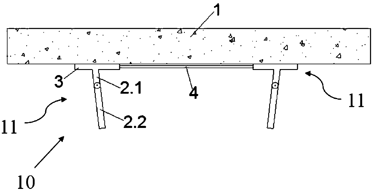
[0027] figure 1 It is a structural schematic diagram of a bridge monitoring device according to Embodiment 1 of the present invention.

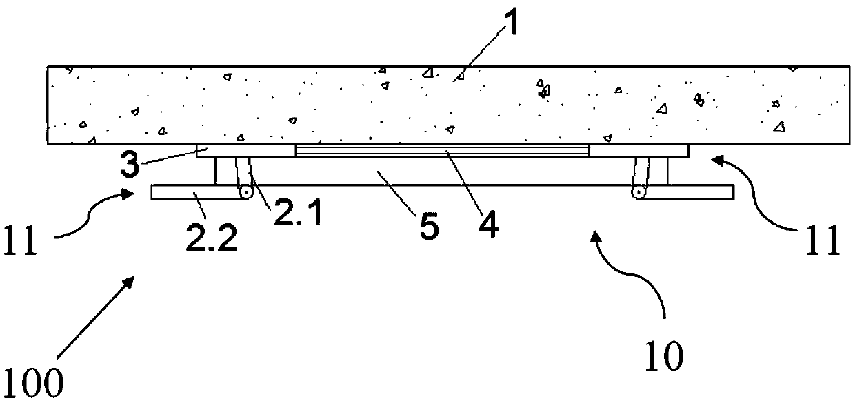
[0028] Such as figure 1 As shown, the bridge monitoring device 100 of this embodiment is used to detect the bridge 1 as the structure to be tested, and includes a strain sensor 5 and a quick installation device 10 for a self-locking inclination strain sensor.

[0029] Wherein, the strain sensor 5 is in the shape of a cuboid, and a through fixing hole is provided on each of its two ends in the length direction;

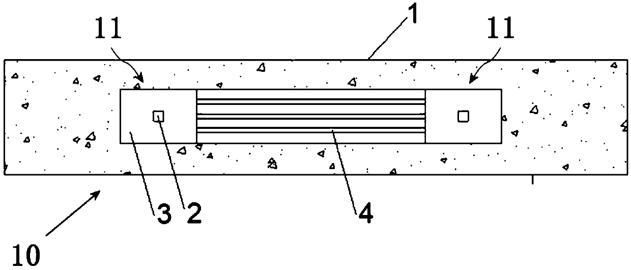
[0030] figure 2 It is a schematic structural diagram of a self-locking inward-facing strain sensor quick installation device according to Embodiment 1 of the present invention, image 3 It is a schematic bottom-view structure diagram of the self-locking inclining strain sensor quick installation device according to Embodiment 1 of the present invention.

[0031] Such as figure 2 and image 3 As shown, the self-locking inclinat...

Embodiment 2

[0058] In the second embodiment, the same structures as those in the first embodiment are assigned the same symbols and the same descriptions are omitted.

[0059] The structural difference between the second embodiment and the first embodiment lies in the connection structure between the upper link 2.1 and the lower link 2.2.

[0060] Figure 6 It is an enlarged schematic view of the connection structure between the upper link and the lower link in the second embodiment of the present invention.

[0061] Such as Figure 6 As shown, the upper connecting rod 2.1 and the lower connecting rod 2.2 in this embodiment are also rotationally connected through the rotating shaft, and the upper connecting rod 2.1 is also provided with a recessed part 2.1.1 at the position of the rotating shaft.

[0062] Different from Embodiment 1, the protrusion 2.2.2 provided on the lower link 2.2 is a circular protrusion corresponding to the recess 2.1.1, and the inner wall of the recess 2.1.1 is p...


PUM


Abstract

The invention aims at providing a sensor fixing mechanism that is convenient to install and does not generate an installation position deviation. The device comprises two fixing components separatelycorresponding to two fixing holes; and at least one connector, wherein each fixing component is provided with a substrate fixed at a predetermined position and a connection rod fixed on the substrate;the connection rod is composed of an upper connection rod and a lower connection rod rotationally connected via a rotation shaft, and is inclined inward, so that after the lower connection rod and the upper connection rod pass through the fixing hole, the lower connection rod can rotate towards the direction of a strain sensor and thus the strain sensor is fixed and enters a pretension state; theconnector is a weak connector; the substrates of the two fixing components are mutually connected via the connector. The sensor fixing mechanism provided by the invention has the advantages of beingsimple to install and not prone to generate installation position error. Furthermore, the invention also provides a bridge monitoring device including the sensor fixing mechanism.

Description

technical field [0001] The invention belongs to the field of structure monitoring, and relates to a sensor fixing mechanism and a bridge monitoring device containing the sensor fixing mechanism, in particular to a self-locking inward-facing strain sensor quick installation device and a bridge monitoring device. Background technique [0002] Strain sensors can measure the deformation of structures by converting mechanical deformation into electrical signals, so they are widely used in the field of structural monitoring. [0003] When in use, the strain sensor needs to be firmly fixed to the surface of the structure to be measured, so that the strain sensor and the structure deform cooperatively and ensure that the strain sensor does not fall off. The currently commonly used strain sensor has two through fixing holes, and its fixing device includes two bolts and nuts with a base. The specific installation method is: paste the base with the bolts on the surface of the structure...

Claims


Application Information

Patent Timeline
IPC IPC(8): G01B21/32G01B5/00
CPCG01B5/0002G01B21/32
Inventor 夏烨雷晓鸣孙利民淡丹辉程纬
Owner TONGJI UNIV
Why Eureka
Try Eureka