
A Dual Frequency Differential Bandpass Filter

A filter and frequency difference technology, which is applied in the microwave and radio frequency fields, can solve the problems of insufficient common-mode signal suppression effect and poor out-of-band selectivity of balanced dual-passband filters, and achieves improved out-of-band selectivity and small size , to achieve the effect of transition transmission

Active Publication Date: 2020-08-04
XIDIAN UNIV
View PDF7 Cites 0 Cited by
  • Summary
  • Abstract
  • Description
  • Claims
  • Application Information

AI Technical Summary

Problems solved by technology

However, the common-mode signal suppression effect of the balanced dual-passband filter is still not significant enough, and there are only two transmission zeros outside the band, and the selectivity outside the band is poor.

Method used


Image

  • A Dual Frequency Differential Bandpass Filter
  • A Dual Frequency Differential Bandpass Filter
  • A Dual Frequency Differential Bandpass Filter

Examples


Embodiment Construction

[0026] The present invention will be further described in detail below in conjunction with the accompanying drawings and specific embodiments.

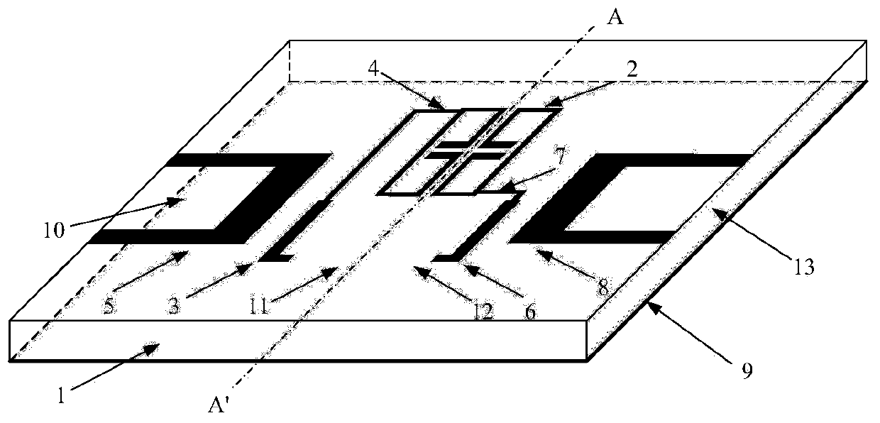
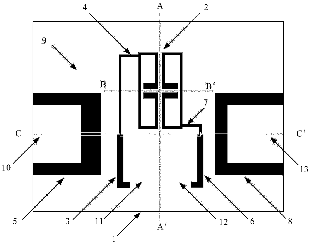
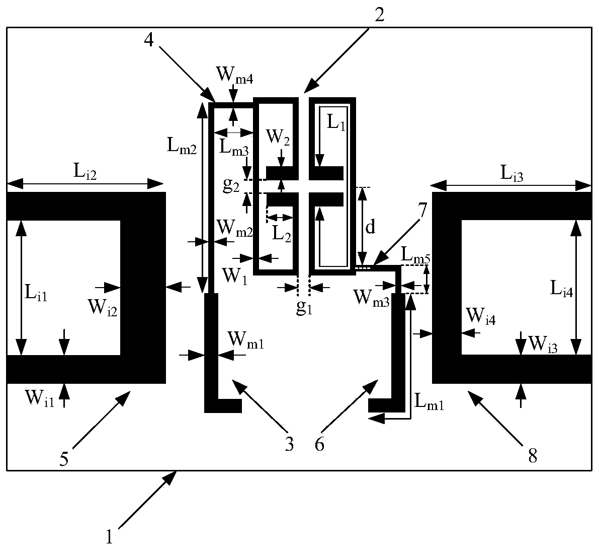
[0027] refer to figure 1 , figure 2 , image 3 and Figure 4, a dual-frequency differential bandpass filter, including a dielectric substrate 1, the upper surface of the dielectric substrate 1 is printed with a microstrip resonator, the microstrip resonator is composed of a rectangular split resonant ring and two rectangular openings Folded stepped impedance split resonant ring 2 formed by connecting folded branches with different widths of the resonant ring is used to achieve dual-frequency characteristics. The axis BB' is symmetrical, and the axis BB' is perpendicular to the axis AA'; the first stepped impedance microstrip line 3, the first uniform impedance microstrip line 4 and the U-shaped input microstrip line are printed on one side of the axis AA' 5. The other side is printed with a second stepped impedance microstrip lin...


PUM

PropertyMeasurementUnit
thicknessaaaaaaaaaa
lengthaaaaaaaaaa
lengthaaaaaaaaaa

Abstract

The invention provides a dual frequency differential band-pass filter, aiming at improving out-of-band selectivity and common mode rejection degree of a dual frequency differential band-pass filter. The band-pass filter includes a dielectric substrate and a metal grounding plate. The upper surface of the dielectric substrate is printed with two folded stepped impedance split-ring resonators with opposite openings which are symmetric about an axis AA' and are used as a resonator. A side of the axis AA' is printed with a first stepped impedance microstrip line, a first uniform impedance microstrip line, and a U-shape input microstrip line. The other side is printed with a second stepped impedance microstrip line, a second uniform impedance microstrip line, and a U-shaped output microstrip line, wherein the two uniform impedance microstrip lines and the folded stepped impedance split-ring resonators on the same side are directly connected. The lower surface of the dielectric substrate isprinted with a metal floor. One side of projection of the axis AA' on the metal floor is etched with a first stepped impedance slit line and the second stepped impedance slit line which are connectedto each other, and the other side is etched with a third stepped impedance slit line and a fourth stepped impedance slit line which are connected to each other.

Description

technical field [0001] The invention belongs to the technical field of microwave and radio frequency, in particular to a dual-frequency differential bandpass filter, which can be applied to the radio frequency front end of a wireless communication system. Background technique [0002] In recent years, with the rapid development of communication technology, filter, as a key frequency selection device, plays an increasingly important role, and its performance often directly affects the quality of the entire communication system. As various communication services emerge in different frequency bands, the microwave frequency band becomes increasingly crowded. At the same time, various communication services appearing in different frequency bands require terminal equipment to have dual / multi-band and multiple functions. In this case, single-frequency filters are no longer practical due to poor adaptability and large size. In order to meet multiple functions of dual / multi-band ter...

Claims


Application Information

Patent Timeline
Patent Type & Authority Patents(China)
IPC IPC(8): H01P1/203
CPCH01P1/20381
Inventor 岳豪杰张晓航胡雪涵魏峰史小卫
Owner XIDIAN UNIV
Learn More