Filter antenna

A filter antenna and filter unit technology, which is applied in the electronic field, can solve the problems of high RF front-end circuit complexity, affecting antenna radiation efficiency and directionality, and mismatching between filters and antenna ports, so as to reduce the difficulty and cost of research and development, reduce Difficulty of signal processing, effect of reducing complexity

Inactive Publication Date: 2019-03-29
SHENZHEN AEROSPACE INNOTECH +1
View PDF6 Cites 0 Cited by
  • Summary
  • Abstract
  • Description
  • Claims
  • Application Information

AI Technical Summary

Problems solved by technology

This method of cascading discrete devices may cause a mismatch between the filter and the antenna port, thereby affecting the radiation efficiency and directivity of the antenna. In addition, in order to realize the cascading of the filter and the antenna, a matching circuit needs to be set up between the two. Make the RF front-end circuit complex

Method used


Image

  • Filter antenna
  • Filter antenna
  • Filter antenna

Examples


Embodiment Construction

[0023] In order to make the purpose, features and advantages of the present application more obvious and understandable, the technical solutions in the embodiments of the present application will be clearly and completely described below in conjunction with the drawings in the embodiments of the present application. Obviously, the described The embodiments are only some of the embodiments of the present application, but not all of them. Based on the embodiments in this application, all other embodiments obtained by those skilled in the art without making creative efforts belong to the scope of protection of this application.

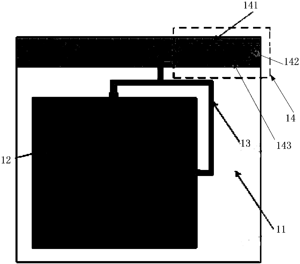
[0024] An embodiment of the present application provides a filter antenna, which can be applied to RFID equipment (such as an RFID reader) or other devices requiring an antenna. see figure 1 , the filter antenna consists of:

[0025] Dielectric substrate 11;

[0026] Radiating unit 12, feeding unit 13 and filtering unit 14 printed on the dielectric su...


PUM


Abstract

The invention provides a filter antenna, to give a filtering function to the antenna. The filter antenna includes: a dielectric substrate; a radiating unit, a feed unit, and a filtering unit printed on the dielectric substrate, wherein the feed unit is electrically connected to the radiating unit and the filtering unit, respectively. The filtering unit is used to filter an input signal. The feed unit is used to feed the signal output by the filtering unit to the radiating unit. The radiating unit is used to radiate a signal from the feed unit.

Description

technical field [0001] The present application relates to the field of electronic technology, in particular to a filter antenna. Background technique [0002] Radio Frequency Identification (RFID) technology, also known as radio frequency identification, is a communication technology that can identify specific targets through radio signals and read and write related data. [0003] In current RFID applications, the filter and antenna are cascaded in the RF front-end circuit as two independent subsystems. This method of cascading discrete devices may cause a mismatch between the filter and the antenna port, thereby affecting the radiation efficiency and directivity of the antenna. In addition, in order to realize the cascading of the filter and the antenna, a matching circuit needs to be set up between the two. This makes the RF front-end circuit complex. Contents of the invention [0004] An embodiment of the present application provides a filter antenna, which is used to...

Claims


Application Information

Patent Timeline
Patent Type & Authority Applications(China)
IPC IPC(8): H01Q1/38H01Q1/50H01Q1/22H01P1/203
CPCH01P1/20336H01Q1/2216H01Q1/38H01Q1/50
Inventor 于波黄新利贺卫冯汉炯杨正明闫泽涛
Owner SHENZHEN AEROSPACE INNOTECH
Why Eureka
Try Eureka