Bridgeless PFC circuit current sampling device and control method thereof

A technology of current sampling and control method, which is applied in the direction of measuring device, current only measurement, current/voltage measurement, etc. It can solve the problems of increased number of electronic components, large number of devices, complex signal processing, etc., and achieves signal processing with little difficulty, Reduce electronic components and overcome the effect of complex structure

Inactive Publication Date: 2016-04-27
ZHUHAI GREE REFRIGERATION TECH CENT OF ENERGY SAVING & ENVIRONMENTAL PROTECTION
View PDF8 Cites 2 Cited by
  • Summary
  • Abstract
  • Description
  • Claims
  • Application Information

AI Technical Summary

Problems solved by technology

[0004] Patent No. 201210453486.5 discloses a bridgeless PFC circuit inductor current sampling device and its control method, but the circuit uses three current acquisition units, the hardware circuit is more complex, and there are many electronic components
[0005] Patent No. 201110077298.2 discloses a bridgeless PFC circuit input current detection method and device, but the method realizes positive and negative half-cycle current sampling by introducing a positive half-cycle shunt unit and a negative half-cycle shunt unit. There are many devices introduced and the circuit is complicated
[0006] The patent No. 201420365505.3 discloses a bridgeless PFC converter. The current sampling unit of this circuit uses a sampling resistor, and the collected current signal is subsequently processed by the TCL2272 operational amplifier. The disadvantage is the peripheral circuit devices and the chip itself brought by the operational amplifier. also consumes energy
[0007] Patent No. 201410228723.7 discloses a high-efficiency bridgeless PFC power converter. While retaining the built-in freewheeling diode in the original MOSFET, the circuit adds two MOSFETs with built-in freewheeling diodes. Although it can improve the efficiency However, the number of components is large and the cost is high
[0008] In general, most current sampling methods for realizing bridgeless PFC current use two or more current sampling units (such as figure 1 As shown, the switch tubes S1 and S2 include controllable switch tubes and built-in freewheeling diodes), resulting in an increase in the number of electronic components, increased cost, and complicated signal processing; the circuit structure has also been improved, but the current sampling unit uses sampling Resistor sampling needs subsequent processing such as amplification by op amp. This processing circuit brings many electronic components, cost, and volume problems that cannot be underestimated.
[0009] In the existing technology, there are defects such as complex structure, high cost and difficult signal processing

Method used


Image

  • Bridgeless PFC circuit current sampling device and control method thereof
  • Bridgeless PFC circuit current sampling device and control method thereof

Examples


Embodiment Construction

[0032] In order to make the purpose, technical solution and advantages of the present invention clearer, the technical solution of the present invention will be clearly and completely described below in conjunction with specific embodiments of the present invention and corresponding drawings. Apparently, the described embodiments are only some of the embodiments of the present invention, but not all of them. Based on the embodiments of the present invention, all other embodiments obtained by persons of ordinary skill in the art without making creative efforts belong to the protection scope of the present invention.

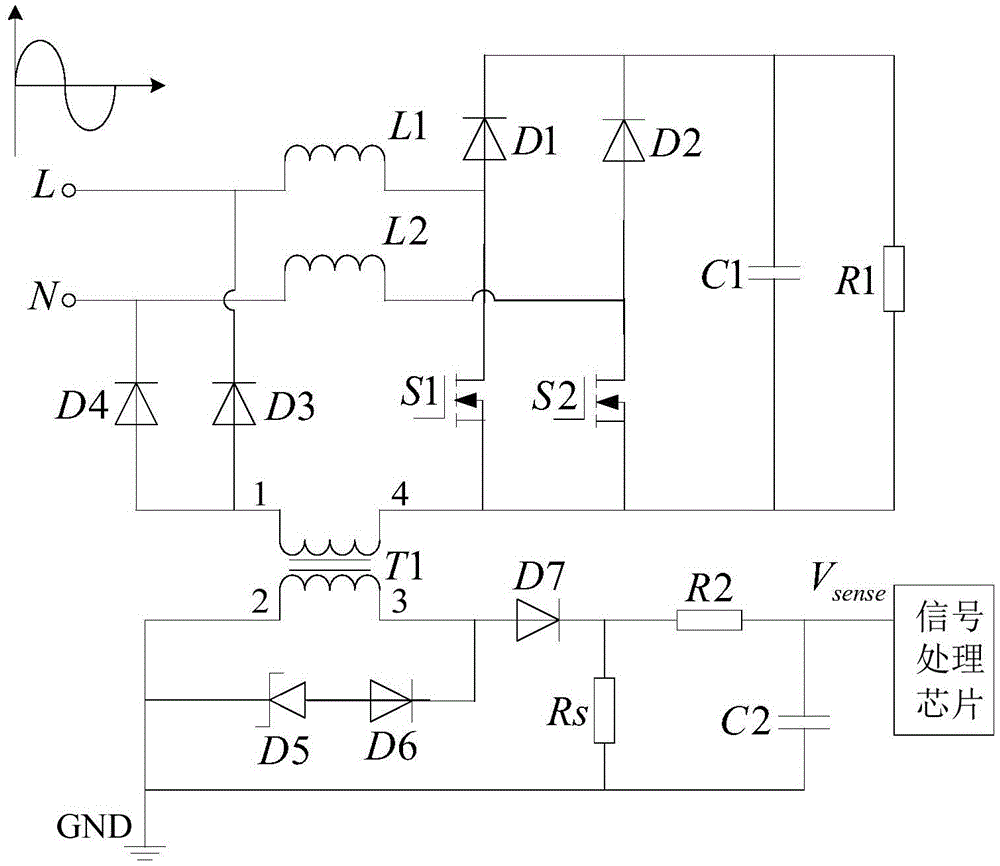
[0033] According to an embodiment of the present invention, a current sampling device for a bridgeless PFC circuit is provided, such as figure 2 A schematic structural view of an embodiment of the device of the present invention is shown. The current sampling device of the bridgeless PFC circuit includes:

[0034] It is sequentially connected to the current tra...


PUM


Abstract

The invention discloses a bridgeless PFC circuit current sampling device and a control method thereof. The bridgeless PFC circuit current sampling device comprises a current transformer (T1) and a current sampling module which are sequentially connected with a bridgeless PFC circuit, wherein the bridgeless PFC circuit is a dual-Boost bridgeless circuit, and a freewheel diode in the bridgeless PFC circuit is set to be a corresponding circuit access point; a first connecting end (1) of a primary side coil of the current transformer (T1) is connected to a low-frequency current backflow end of the dual-Boost bridgeless circuit, and a second connecting end (4) of the primary side coil of the current transformer (T1) is connected to a switching tube of the dual-Boost bridgeless circuit; and the current sampling module is connected between both ends of a secondary side coil of the current transformer (T1). The bridgeless PFC circuit current sampling device and the control method thereof can overcome defects such as complex structure, high cost and great signal processing difficulty in the prior art, and achieve the beneficial effects of simple structure, low cost and small signal processing difficulty.

Description

technical field [0001] The present invention relates to the technical field of electronic circuits, in particular to a current sampling device of a bridgeless PFC circuit and a control method thereof. Background technique [0002] PFC (PowerFactorCorrection, power factor correction) refers to the relationship between effective power and total power consumption (apparent power), that is, the ratio of effective power divided by total power consumption (apparent power). Basically, the power factor can measure the degree to which electricity is effectively utilized. When the value of the power factor is larger, it means that the power utilization rate is higher. [0003] The bridgeless PFC structure has received extensive attention because of its advantages of reducing the rectifier bridge and greatly reducing the system loss. The basic bridgeless PFC circuit topology has the difficulty of current reversal in the positive and negative half cycles, which makes the detection of t...

Claims


Application Information

Patent Timeline
Patent Type & Authority Applications(China)
IPC IPC(8): G01R19/00
CPCG01R19/0092
Inventor 苏勇雪张东盛刘亚祥程海珍刘玲赵杰
Owner ZHUHAI GREE REFRIGERATION TECH CENT OF ENERGY SAVING & ENVIRONMENTAL PROTECTION
Why Eureka
Try Eureka