Flexible display panel and display device

A flexible display and panel technology, applied in the direction of identification devices, instruments, etc., can solve the problem that the proportion of the display area is not high enough, and achieve the effect of increasing the proportion of the display area, narrowing the border, and enhancing the visual effect

Inactive Publication Date: 2019-04-02
EVERDISPLAY OPTRONICS (SHANGHAI) CO LTD
View PDF11 Cites 24 Cited by
  • Summary
  • Abstract
  • Description
  • Claims
  • Application Information

AI Technical Summary

Problems solved by technology

However, it still cannot meet the requirements of narrow borders, and the proportion of the display area is not high enough.

Method used


Image

  • Flexible display panel and display device
  • Flexible display panel and display device
  • Flexible display panel and display device

Examples


Embodiment Construction

[0023] The present invention will be further described in detail below in conjunction with the accompanying drawings and embodiments. It should be understood that the specific embodiments described here are only used to explain the present invention, but not to limit the present invention. In addition, it should be noted that, for the convenience of description, only some structures related to the present invention are shown in the drawings but not all structures.

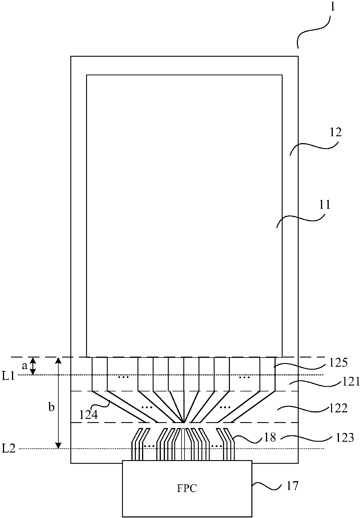
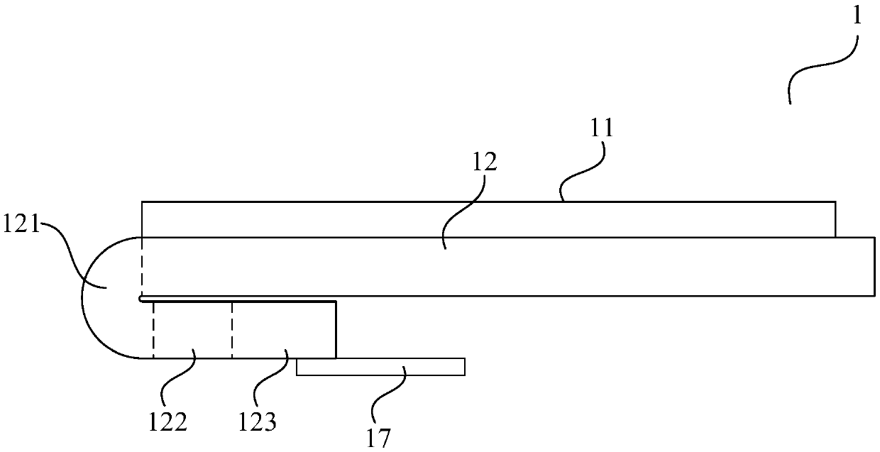
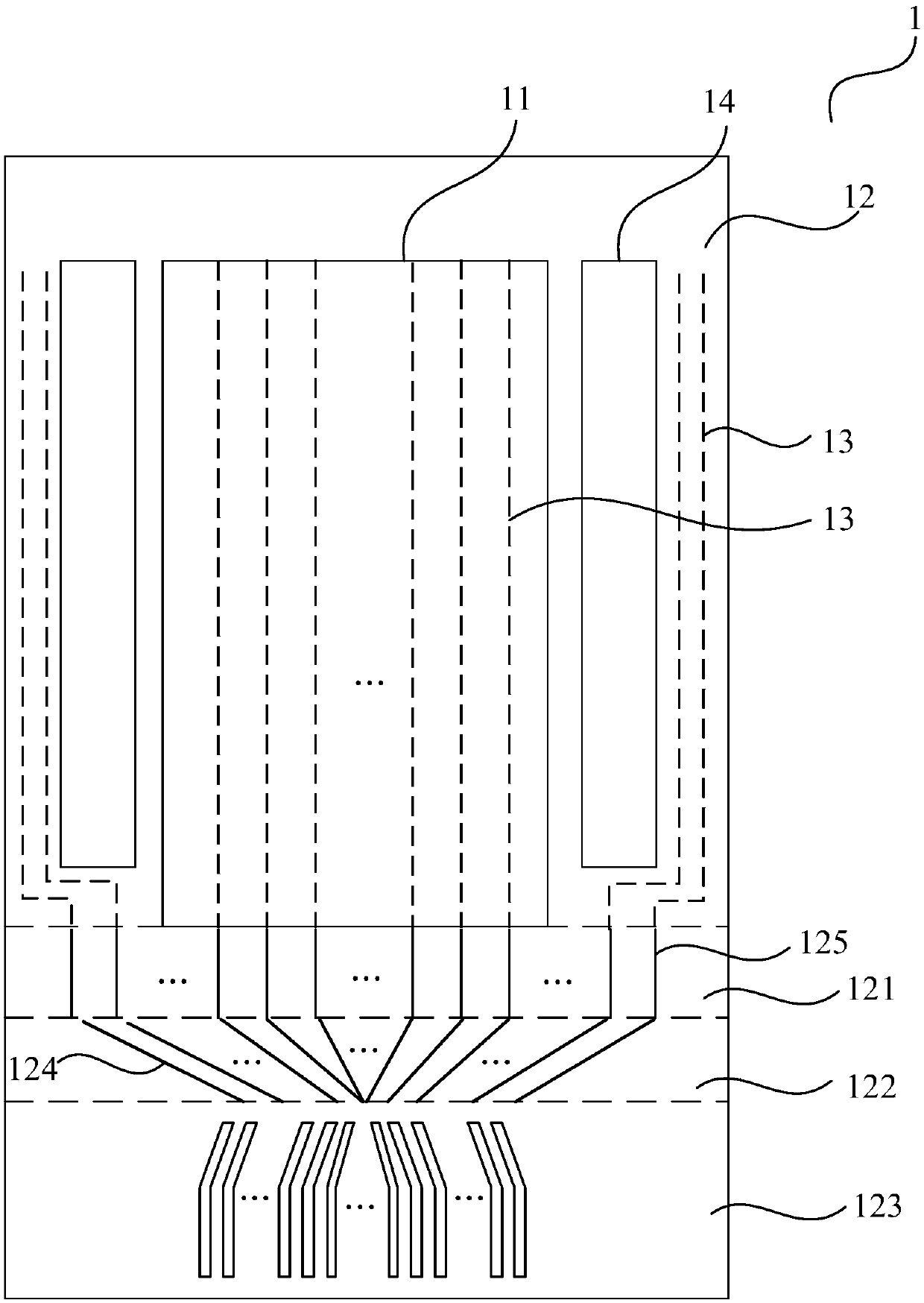
[0024] An embodiment of the present invention provides a flexible display panel, referring to figure 1 and figure 2 , figure 1 It is a schematic plan view of the bending area of ​​a flexible display panel before bending provided by an embodiment of the present invention, figure 2 It is a schematic diagram of the structure of the flexible display panel after bending in the bending area provided by the embodiment of the present invention, combined with figure 1 and figure 2 As shown, the flexible display pane...


PUM


Abstract

The embodiment of the invention discloses a flexible display panel and a display device. The flexible display panel comprises a display area and a non-display area surrounding the display area, wherein the non-display area on one side of the display area comprises a bending area, a fan-out area and a binding area; the fan-out area is positioned between the bending area and the binding area, the fan-out area is arranged adjacent to the display area, and the binding area is arranged far away from the display area; and after the bending area is bent, the fan-out area, the binding area and at least part of the bending area attach to the non-display side of the flexible display panel. According to the technical scheme provided by the embodiment of the invention, the flexible display panel has the narrower frame, and thus the proportion of the display area of the display panel is improved.

Description

technical field [0001] Embodiments of the present invention relate to the field of organic light-emitting display technologies, and in particular, to a flexible display panel and a display device. Background technique [0002] The existing display panel is generally divided into a display area and a non-display area. The display signal is transmitted to the driver chip through a flexible printed circuit (FPC) via a bonding pad, and then the driver chip passes through the fan-out area in the non-display area. The wiring is input to the corresponding data signal line in the display area, and there is usually another layer of metal above the wiring in the fan-out area as the ELVDD wiring of the anode power line of the organic light-emitting display panel, and the anode power line is generally strip-shaped. [0003] The general distance from the beginning area of ​​the fan-out area to the end area of ​​the bonding pad is about 5mm, and then the FPC can be bent to the back of the...

Claims


Application Information

Patent Timeline
Patent Type & Authority Applications(China)
IPC IPC(8): G09F9/30
CPCG09F9/301
Inventor 盛晨航徐海燕
Owner EVERDISPLAY OPTRONICS (SHANGHAI) CO LTD
Why Eureka
Try Eureka