Electronically controllable pneumatic brake system in a utility vehicle and method for electronically controlling a pneumatic brake system in a utility vehicle

A pneumatic braking, electronic control technology, applied in the direction of brake transmission, control valve and air release valve, brake, etc., can solve the problem of difficult modification, increase assembly cost and cost, etc.

Active Publication Date: 2019-04-02
WABCO EURO BVBA SPRL
View PDF9 Cites 2 Cited by
  • Summary
  • Abstract
  • Description
  • Claims
  • Application Information

AI Technical Summary

Problems solved by technology

The disadvantage of all these solutions is that the additional pneumatic components increase the assembly effort and costs and are also very difficult to retrofit

Method used


Image

  • Electronically controllable pneumatic brake system in a utility vehicle and method for electronically controlling a pneumatic brake system in a utility vehicle
  • Electronically controllable pneumatic brake system in a utility vehicle and method for electronically controlling a pneumatic brake system in a utility vehicle
  • Electronically controllable pneumatic brake system in a utility vehicle and method for electronically controlling a pneumatic brake system in a utility vehicle

Examples


Embodiment Construction

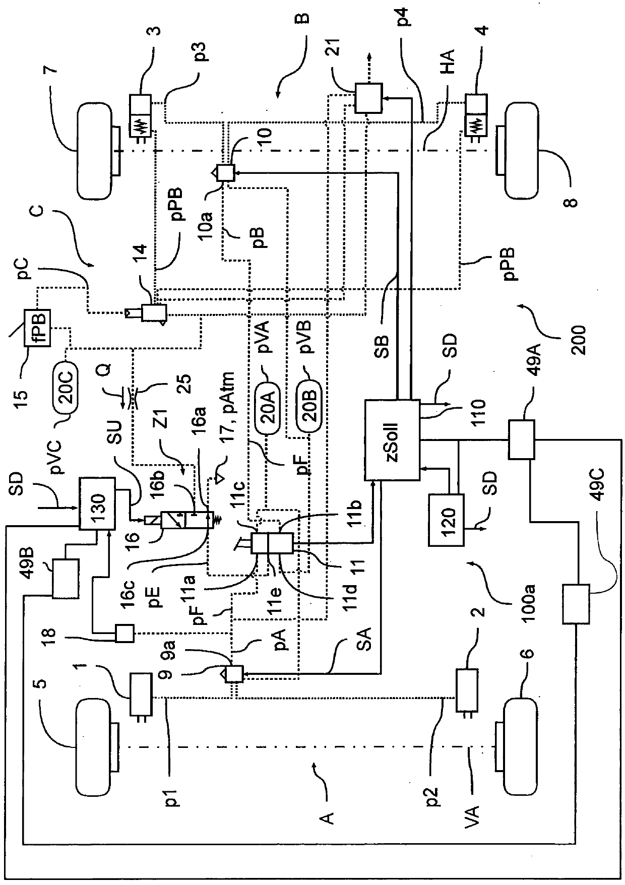
[0050] in accordance with Figure 1a In the embodiment of the present invention, a section of an electropneumatic braking system 100a of a vehicle 200, in particular a commercial vehicle, is shown as a block diagram, wherein the electropneumatic braking system is implemented as an EBS braking system 100a, that is to say brake pre-braking It is assumed to be implemented purely electrically in normal operation. For this purpose, EBS braking system 100 a has four wheel brakes 1 , 2 , 3 , 4 which are used to decelerate wheels 5 , 6 , 7 , 8 of vehicle 200 . For deceleration, three brake circuits A, B, C are provided, each of which is assigned a pressure medium reservoir 20A, 20B, 20C in order to supply the respective brake circuit A, B, C with pressure medium and thus be able to A build-up of brake pressures p1 , p2 , p3 , p4 , pPB for the respective wheel brakes 1 , 2 , 3 , 4 is achieved. In each pressure medium accumulator 20A, 20B, 20C there is a corresponding reserve pressure ...


PUM


Abstract

The invention relates to an electronically controllable pneumatic brake system in a vehicle (200), comprising at least: wheel brakes (1, 2, 3, 4), wherein a service-brake brake pressure (p1, p2, p3, p4) can be predefined to the wheel brakes (1, 2, 3, 4) of axle modulators (9, 10) as a function of a service-brake control pressure (pA, pB), a foot brake valve (11) for pneumatically predefining the service-brake control pressure (pA, pB), wherein the service-brake control pressure (pA, pB) can be generated by the foot brake valve (11) as a function of a mechanical predefinition or as a function of an electro-pneumatic predefinition, and a bypass valve arrangement (16, 19) for predefining a foot-brake input pressure (pE), serving as an electro-pneumatic predefinition, to the footbrake valve (11), wherein in a first switched position (Z1) the bypass valve arrangement (16, 19) predefines a low-pressure level, and in a second switched position (Z2) it predefines a high pressure level, as an electro-pneumatic predefinition to the foot brake valve. The foot brake input pressure (pE) which is predefined by the bypass valve arrangement (16) as an electro-pneumatic predefinition (V2) can be passed through via the venting space and a working space of the footbrake valve (11) as a service-brake control pressure (pA, pB).

Description

technical field [0001] The invention relates to an electronically controllable pneumatic braking system in a commercial vehicle and to a method for electronically controlling a pneumatic braking system. Background technique [0002] In vehicles with a pneumatic braking system, in particular commercial vehicles, the control unit (ECU) can electronically actuate the axle modulators assigned to the axles in order to control the brake pressure. In this case, the electronic control takes place either as a function of the driver's intention preset via the foot brake valve or as a function of an automatically preset target deceleration of the vehicle. The axle modulator then pneumatically generates the corresponding service brake pressure, which is regulated on the brake cylinders of the service brakes of the braking system. [0003] Alternatively, the axle modulator can also be actuated pneumatically in that a service brake control pressure corresponding to the driver's will is p...

Claims


Application Information

Patent Timeline
Patent Type & Authority Applications(China)
IPC IPC(8): B60T13/68
CPCB60T7/04B60T13/683B60T15/027B60T15/043B60T7/06B60T13/586B60T17/227
Inventor 奥利弗·伍尔夫
Owner WABCO EURO BVBA SPRL
Why Eureka
Try Eureka