LED headlight

A technology for headlights and heat conducting elements, applied in the direction of headlights, lighting devices, vehicle lighting systems, etc., can solve problems such as hindering the calibration of headlights, solution consumption efficiency, etc., to achieve space-saving, maintenance-free, durable cooling system Effect

Active Publication Date: 2014-04-23
OSRAM GMBH
View PDF3 Cites 0 Cited by
  • Summary
  • Abstract
  • Description
  • Claims
  • Application Information

AI Technical Summary

Problems solved by technology

But these solutions are relatively expensive and inefficient
It is also relatively bulky and thus prevents the often desired alignment of the headlights

Method used


Image

  • LED headlight
  • LED headlight
  • LED headlight

Examples


Embodiment Construction

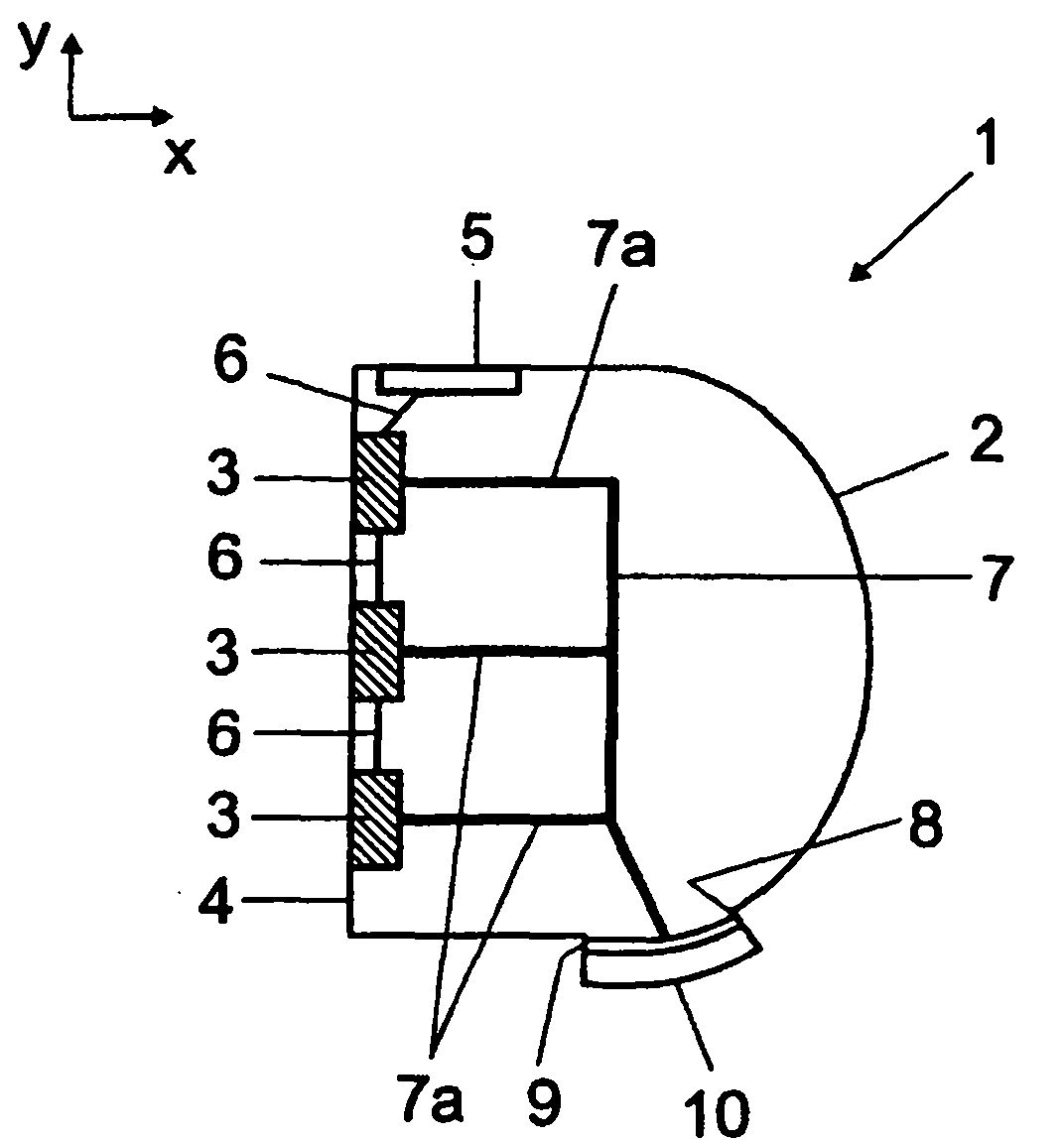
[0029] figure 1 A sectional view of an LED headlight 1 is shown, in which three lamps (LED lamps) 3 equipped with light-emitting diodes (LED lamps) are included as light sources in a headlight housing 2 made of plastic, The lamp emits its light through the optically transparent front face 4 . The LED light 3 can be used, for example, as low beam, high beam or turn signal. The LED lamps 3 are jointly connected to the electrical interface 5 through a cable 6 . The LED lamp 3 is thermally connected by means of jointly movable heat pipes 7 to a heat transfer connection 9 with good thermal conductivity, which consists of iron, copper, aluminum or alloys thereof. More precisely, the heat pipe 7 is placed on the one hand on the metal seat of the corresponding LED string (not shown) of the associated LED lamp 3, that is to say indirectly but thermally well connected to the LEDs of the LED string as the main heat source. connect. For this purpose, heat pipes 7 with a copper jacket ...


PUM


Abstract

An LED headlight may include at least one heat-conducting element that extends from at least one heat source located in a headlight housing to at least one cooling element in such a way as to make thermal contact and which is arranged at least partially outside on the headlight housing, the heat-conducting element being movable.

Description

technical field [0001] The invention relates to an LED headlamp, especially for automobiles, especially motor vehicles. Background technique [0002] Especially when using LEDs in motor vehicle headlights, it may be necessary to cool the LED light source due to thermal problems. [0003] The solution hitherto has been passive cooling by using cooling bodies in the headlamp. This is assisted in part by active components such as fans, which circulate air within the headlight housing. But these solutions are relatively expensive and inefficient. It is also relatively bulky and thus prevents the often desired alignment of the headlights. Contents of the invention [0004] It is an object of the invention to provide a simple, space-saving and efficient cooling of LED headlights. [0005] This object is achieved by means of an LED headlight according to claim 1 . [0006] LED motor vehicle headlights of this type have at least one light-emitting diode (LED) as light source....

Claims


Application Information

Patent Timeline
Patent Type & Authority Patents(China)
IPC IPC(8): F21V29/02
CPCF21V29/30F21V29/26F21S48/335F21V29/246F21S48/326F21V29/02F21S48/325F21V29/006F21S48/328F21Y2101/02F21V29/004F21S48/115F21V29/56F21V29/71F21V29/89F21Y2115/10F21S41/151F21S45/48F21S45/33
Inventor 彼特·弗赖克里斯蒂安·迈尔
Owner OSRAM GMBH
Why Eureka
Try Eureka