Method and device for data transmission in next generation cellular network
What is AI technical title?
AI technical title is built by PatSnap AI team. It summarizes the technical point description of the patent document.
A technology for receiving data and downlinking, which is applied in the field of data transmission and can solve the problems of no judgment and no assertion.
Active Publication Date: 2021-03-23
SAMSUNG ELECTRONICS CO LTD
View PDF9 Cites 0 Cited by
Summary
Abstract
Description
Claims
Application Information
AI Technical Summary
This helps you quickly interpret patents by identifying the three key elements:
Problems solved by technology
Method used
Benefits of technology
Problems solved by technology
No determination has been made, and no assertion is made, as to whether any of the above would be applicable as prior art with respect to the present disclosure
Method used
Image
Click on the blue label to locate the original text in one second.
Reading with bidirectional positioning of images and text.
[0072] Figure 5 The figure shows an example of a configuration indicated based on a symbol bitmap according to an embodiment of the present disclosure.
[0073] refer to Figure 5 , if there are N symbols in a given TTI duration, then a bitmap {b 0 ,b 1 ,...,b n ,b n+1 ,...,b N-1} can be used e.g. by setting b n = 1 or 0 to explicitly indicate whether the nth symbol is allocated. This requires N bits for indicating each symbol. For example, if N=14, an indication with a 14-bit bitmap is necessary.
Embodiment 2
[0074] Embodiment 2: start symbol index, end symbol index (or the quantity of symbol)
[0075] Figure 6 Figure illustrates an example of a configuration-based indication of a start symbol and an end symbol according to an embodiment of the disclosure.
[0076] refer to Figure 6 , if there are N symbols in a given TTI duration, then (n start ,n symbol ) indication can be used to indicate that there are from n start start to n end The indexed symbols are assigned. Alternatively, (n start , n symbol ) indication can be used to indicate from nstart start n symbol consecutive symbols are assigned, i.e., until the index (n start +n symbol -1) until the code unit. In other words, information about the start symbol and the duration of the assigned consecutive symbols can be signaled. this requires bits are used for indication. For example, if N=14, an indication with 8 bits is necessary.
Embodiment 3
[0077] Embodiment 3: Indication of consecutively allocated symbols
[0078] Figure 7 The diagram illustrates an example of a configuration-based indication of consecutively allocated symbols according to an embodiment of the disclosure.
[0079] refer to Figure 7 , to further reduce overhead, a tree-based signaling method can be used to indicate if consecutive symbols are always assigned. A resource indication value (RIV) can be signaled in order to derive the index n of the starting symbol start and the number of assigned consecutive symbols n symbol . RIV and n start / n symbol The relationship between can be expressed as follows:
[0080] -if Then RIV=N(n symbol -1)+n start
[0081] - else (i.e., Then RIV=N(N-n symbol +1)+(N-1-n start )
[0082] this requires bits are used for indication. For example, if N=14, an indication with 7 bits is necessary. exist Figure 7 An example in the case of N=6 is shown in .
PUM
Abstract
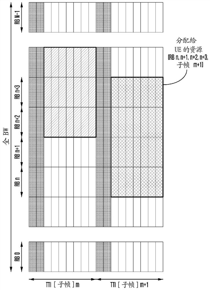
Provided are a communication method and system for fusing a 5th generation (5G) communication system supporting a higher data rate beyond a 4th generation (4G) system with a technology for the Internet of Things (IoT). The communication method and system can be applied to smart services based on 5G communication technology and IoT related technologies, such as smart home, smart building, smart city, smart car, connected car, health care, digital education, smart retail, security and security services . A method for receiving data by a user equipment (UE) is provided. The method includes receiving, from a base station, information on radio resources allocated to a UE, and receiving data from the base station based on the information on the radio resources. Radio resources are associated with a number of symbols in the time domain and a number of resource block groups in the frequency domain. The information on the radio resource includes at least one of first information on a start symbol or second information on a size of each of the resource block groups.
Description
technical field [0001] The present disclosure relates to methods and apparatus for data transmission. More specifically, the present disclosure relates to resource configuration and scheduling methods in next generation cellular networks. Background technique [0002] In order to meet the demand for wirelessdata traffic that has increased due to the deployment of fourth generation (4G) communication systems, efforts have been made to develop improved fifth generation (5G) or quasi-5G communication systems. Therefore, 5G or quasi-5G communication system is also called "Beyond (Beyond) 4G network" or "Long Term Evolution (LTE) system". The 5G communication system is considered to be implemented in a higher frequency (mmWave) band (eg, 60GHz band) in order to achieve higher data rates. In order to reduce the propagation loss of radio waves and increase the transmission distance, beamforming, massive multiple-input multiple-output (MIMO), full-dimensional MIMO (FD-MIMO), arra...
Claims
Application Information
Patent Timeline
Application Date:The date an application was filed.
Publication Date:The date a patent or application was officially published.
First Publication Date:The earliest publication date of a patent with the same application number.
Issue Date:Publication date of the patent grant document.
PCT Entry Date:The Entry date of PCT National Phase.
Estimated Expiry Date:The statutory expiry date of a patent right according to the Patent Law, and it is the longest term of protection that the patent right can achieve without the termination of the patent right due to other reasons(Term extension factor has been taken into account ).
Invalid Date:Actual expiry date is based on effective date or publication date of legal transaction data of invalid patent.

