Multifunctional ventilator control device

A technology for a control device and a ventilator, which is applied in the field of ventilators and can solve the problems of poor dustproof effect and non-removal.

Pending Publication Date: 2019-04-05
河南辉瑞生物医电技术有限公司
View PDF7 Cites 0 Cited by
  • Summary
  • Abstract
  • Description
  • Claims
  • Application Information

AI Technical Summary

Problems solved by technology

[0003] The purpose of the present invention is to provide a multifunctional ventilator control device to solve the problems of poor dustproof effect and non-detachable problem of the existing ventilator control device

Method used


Image

  • Multifunctional ventilator control device
  • Multifunctional ventilator control device
  • Multifunctional ventilator control device

Examples


Embodiment 1

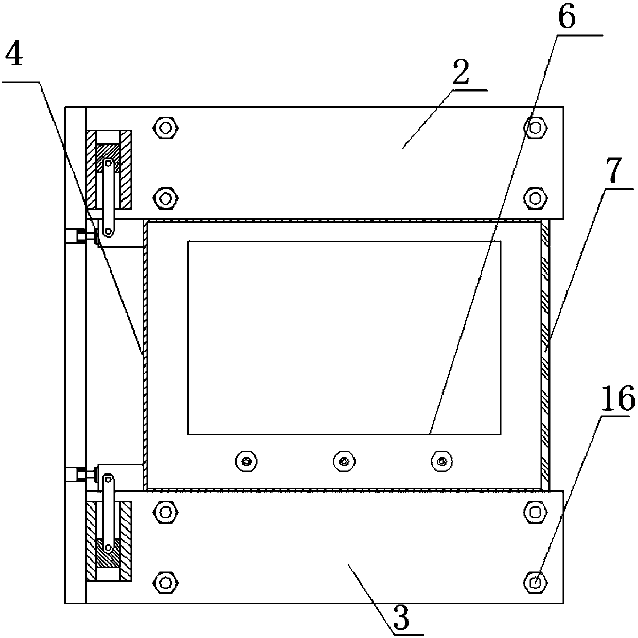
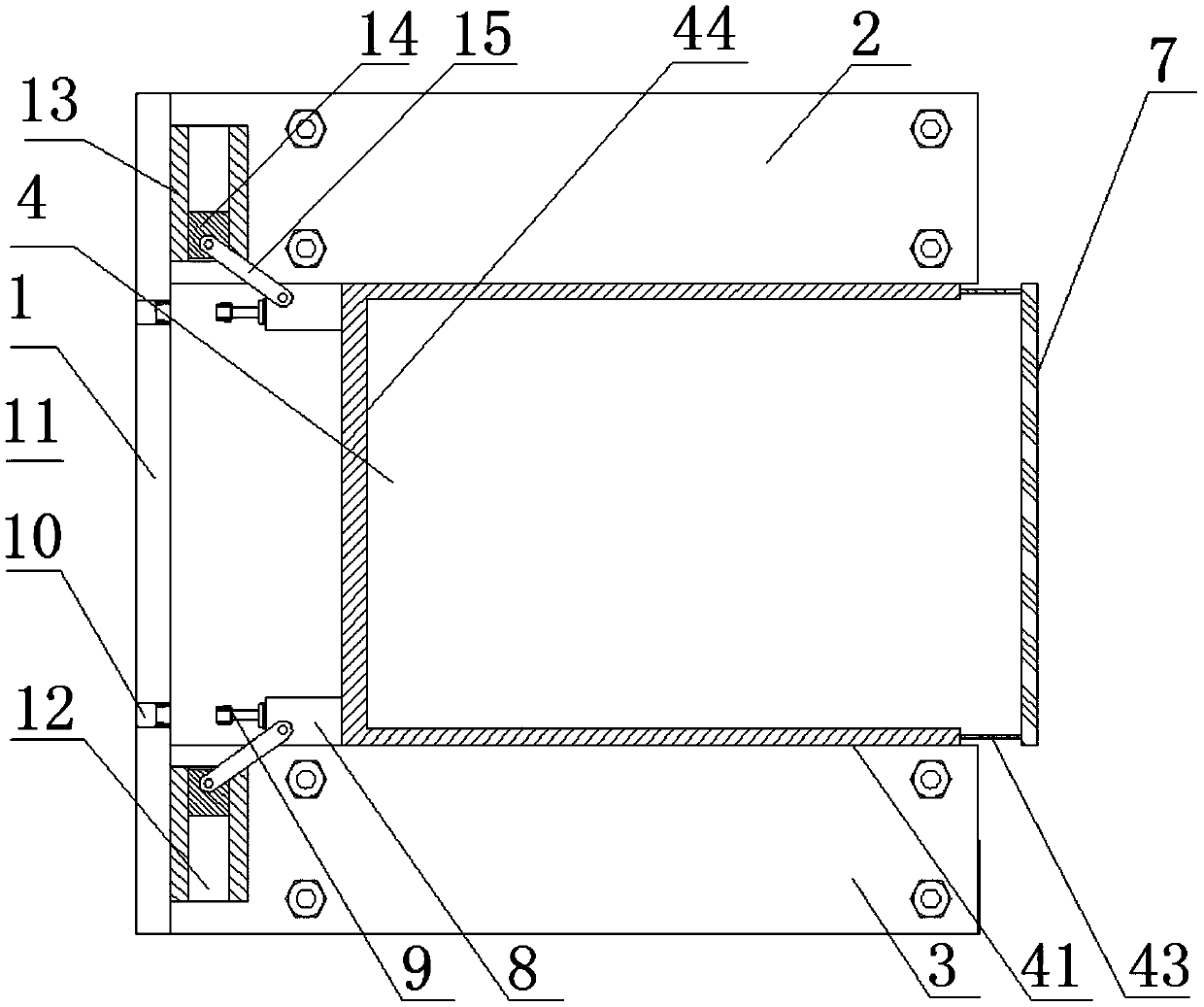
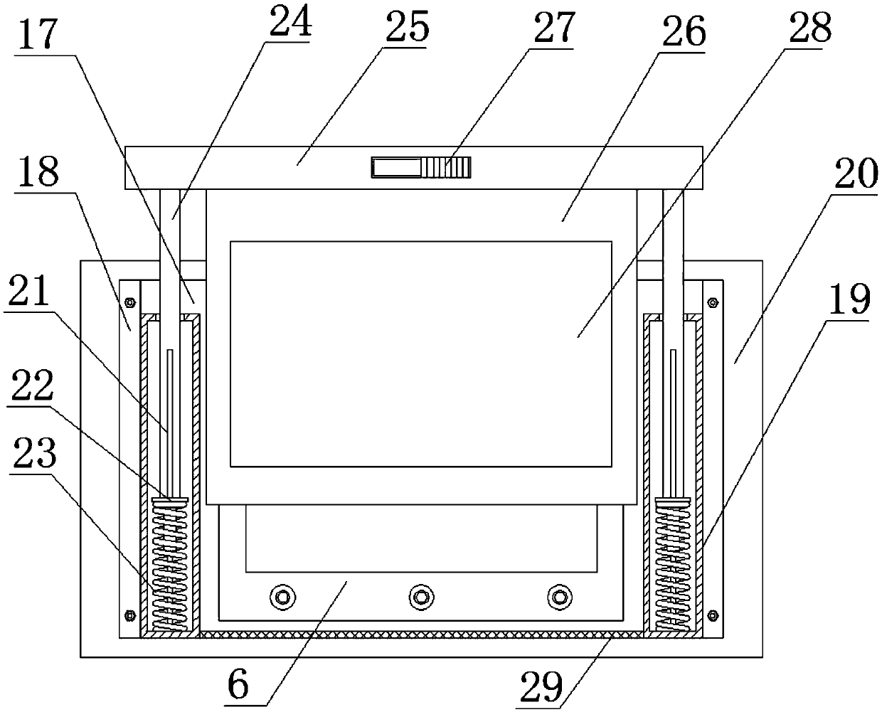
[0038] A multi-functional ventilator control device, comprising a mounting assembly and a control panel assembly, the mounting assembly includes a vertical plate, the upper and lower sides of the right surface of the vertical plate are respectively connected with an upper base and a lower base, and a wall is arranged between the upper base and the lower base. Type mounting seat, the opening direction of the flat type mounting seat is towards the right side of the vertical plate, and the inner surface of the flat type mounting seat is provided with a card slot. A baffle, a sleeve is installed on the side of the baffle, a control plate is installed between the sleeves on the installation plate, a guide rod is connected to the inner bottom wall of the sleeve, a pressure sleeve is set on the guide rod, and a pressure sleeve and a pressure sleeve are located on the guide rod. A spring is set between the inner bottom wall of the sleeve, and a hollow support rod is set on the upper pa...

Embodiment 2

[0040] On the basis of Embodiment 1, through holes are opened on the upper and lower side frames of the square-shaped mounting seat, and a pull rod is sleeved in the through hole, and the other end of the pull rod is connected to a limiting plate. Through this setting, when it is necessary to install the control plate assembly, pull the limit plate away from the vertical plate, and set the bottom plate on the vertical mounting seat to realize the installation of the control plate. After the installation is completed, push the limit plate in the direction close to the vertical plate From the position plate to the flat-shaped mounting seat, make the surrounding of the flat-shaped mounting seat and the limit plate form a closed space to prevent the bottom plate from accidentally falling from the opening direction of the flat-shaped mounting seat, causing damage to the control panel. When it is necessary to disassemble the control panel When assembling, you only need to pull the li...

Embodiment 3

[0042] On the basis of the above-mentioned embodiments, a connecting column is connected to the vertical frame of the Z-type mounting seat, and a taper sleeve is connected to the connecting post. A positioning hole is correspondingly opened in the vertical plate along the axial direction of the taper sleeve. The expansion sleeve matched with the sleeve, the upper base and the lower base are also provided with a mounting groove on the side close to the vertical plate, a slide rail is arranged in the installation groove, a moving block is arranged in the sliding rail, and a connecting rod is hinged on the surface of the moving block, and the connecting rod The other end is hinged to the surface of the connecting column. Through this setting, it is convenient to move the flat-shaped mounting seat left and right, and it is convenient to clamp the bottom plate on the flat-shaped mounting seat, and it is convenient for people to disassemble and install the control panel. After the c...


PUM


Abstract

The invention discloses a multifunctional ventilator control device, belongs to the technical field of ventilators, and aims at solving the problems that in the prior art, the ventilator control device is poor in dust prevention effect and cannot be disassembled. The multifunctional ventilator control device comprises a mounting component and a control flat plate component, wherein the mounting component comprises a vertical plate; the vertical plate is connected with an upper base and a lower base, and a reversed transverse [-shaped mounting base is arranged between the upper base and the lower base; a clamping groove is formed in the inner surface of the reversed transverse [-shaped mounting base; the control flat plate component comprises a bottom plate, and a mounting plate is arrangedon the bottom plate; baffle plates are respectively arranged at the two ends of the mounting plate; a sleeve is arranged on the side face of each baffle plate; a control flat plate is arranged on themounting plate and is positioned between the sleeves; the internal bottom wall of each sleeve is connected with a guide rod; a pressing sleeve sleeves each guide rod; a spring sleeves each guide rod;a hollow support rod sleeves the upper part of each guide rod; one ends of the hollow support rods are connected with the pressing sleeves, and a connecting plate, connected with the other ends of the hollow support rods, is connected with a dust cover; and the bottom plate is arranged on the reversed transverse [-shaped mounting base by means of the clamping groove. The invention is suitable forthe ventilator control device.

Description

technical field [0001] The invention belongs to the technical field of ventilators, and in particular relates to a multifunctional ventilator control device. Background technique [0002] Ventilators are divided into emergency transfer ventilators, therapeutic ventilators, household ventilators, etc. according to their functions. Among them, the therapeutic ventilator is used for respiratory therapy in ICU (Intensive Care Unit), CCU (Coronary Care Unit) and other intensive care units, the emergency transfer ventilator is used for pre-hospital or in-hospital emergency transfer of patients, and the home ventilator is used for home sleep therapy . With the needs of the development of medical and health services, our country is also equipped with a considerable number of ventilators correspondingly. How to better improve their utilization rate and exert better economic benefits requires us to apply scientific and modern management methods to manage. The existing ventilator ca...

Claims


Application Information

Patent Timeline
Patent Type & Authority Applications(China)
IPC IPC(8): A61M16/00
CPCA61M16/00A61M16/0003A61M2209/082A61M2205/502
Inventor 王勇王静余晓丹
Owner 河南辉瑞生物医电技术有限公司
Why Eureka
Try Eureka