An anti-winding and high-voltage isolation structure for a rotary flamethrower wire and a rotary flamethrower

A high-voltage isolation and anti-winding technology, applied in lighting and heating equipment, burners, electrical components, etc., can solve the problems affecting the normal use of flamethrower equipment, wire winding, wire easily damaged, etc., to extend service life, overcome the The effect of wire winding and reducing the failure rate

Active Publication Date: 2020-10-13
SHOWVEN TECH CO LTD
View PDF10 Cites 0 Cited by
  • Summary
  • Abstract
  • Description
  • Claims
  • Application Information

AI Technical Summary

Problems solved by technology

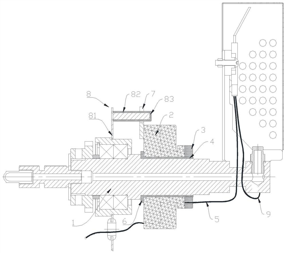
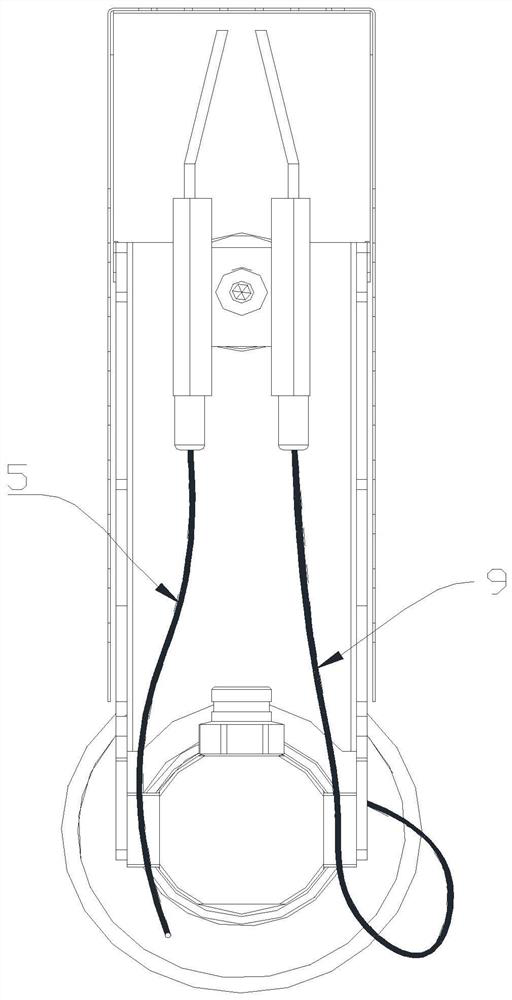
[0003] Existing flame jets can swing back and forth within 180 degrees to spray flames. During the rotation of the flame head, the high-voltage ignition electrodes and high-voltage positive and negative wires are all processed with the usual technical structure. For flame jets that rotate and spray flames, when the flame jet head rotates from 180 degrees to a full circle or even multiple circles, the high-voltage ignition electrode on the flame jet needs to be continuously powered, and the positive and negative wires are rotated throughout the whole circle or even multiple circles. When rotating, the wires will be entangled and repeated many times. After a long time, the wires will be easily damaged, which will affect the normal use of the flamethrower equipment.
[0004] Therefore, how to provide an anti-winding and high-voltage isolation structure for the wires of a rotary flamethrower, which can overcome the problem of wire entanglement during the entire rotation of the flamethrower, has become a technical problem to be solved urgently by those skilled in the art.

Method used


Image

  • An anti-winding and high-voltage isolation structure for a rotary flamethrower wire and a rotary flamethrower
  • An anti-winding and high-voltage isolation structure for a rotary flamethrower wire and a rotary flamethrower

Examples


Embodiment Construction

[0021] In order to enable those skilled in the art to better understand the technical solution in the application, the technical solution in the embodiment of the application will be clearly and completely described below in conjunction with the drawings in the embodiment of the application. Obviously, the described implementation Examples are only some of the embodiments of the present application, but not all of them. Based on the embodiments in this application, all other embodiments obtained by persons of ordinary skill in the art without making creative efforts belong to the scope of protection of this application.

[0022] It should be noted that when an element is referred to as being "fixed" or "disposed on" another element, it may be directly disposed on another element or indirectly disposed on another element; when an element is referred to as being "connected" It may be directly connected to another element or indirectly connected to another element.

[0023] It i...


PUM


Abstract

The application discloses a wire anti-winding and high-voltage isolation structure of a rotary flame thrower. Compared with the prior art, the structure comprises a flame thrower rotating shaft for being in contact with a negative wire of an electrode, a conductive slip ring fixing portion mounted on the flame thrower rotating shaft, and a conductive slip ring rotating portion mounted on the flamethrower rotating shaft and being in contact with the conductive slip ring fixing portion; the conductive slip ring rotating portion is used for guiding a positive wire of the electrode to be in contact with the conductive slip ring fixing portion; wherein the flame thrower rotating shaft is relatively stationary with the conductive slip ring rotating portion; and the flame thrower rotating shaftis movable relative to the conductive slip ring fixing portion. Compared with the prior art, the wire anti-winding and high-voltage isolation structure of the rotary flame thrower provided by the application can overcome the problem of wire winding during the whole rotation jet, prolong the service life of a wire of the flame thrower and reduce the failure rate of the flame thrower. The application also relates to the rotary flame thrower which has the above-described beneficial effects.

Description

technical field [0001] The present application relates to the technical field of the flamethrower, and more specifically, relates to an anti-winding and high-voltage isolation structure for the wire of a rotary flamethrower. The present application also relates to a rotary flamethrower. Background technique [0002] The flamethrower belongs to stage special effects equipment, which is mainly used for special effects display on stages, concerts and other big events to create a warm and dynamic special effects atmosphere. The main working principle of the flamethrower is to transfer the fuel through the pipeline pumping system and spray it out from the flamethrower, atomize the fuel under a certain pumping pressure, and ignite the atomized fuel through a high-pressure ignition device to form a flame effect. There are many types of flamethrowers on the market, mainly including single-head direct injection, multi-head direct injection, shaking head flamethrowers and so on. Amon...

Claims


Application Information

Patent Timeline
Patent Type & Authority Patents(China)
IPC IPC(8): A63J5/02F23D11/10F23D11/36H02G3/04
CPCA63J5/02F23D11/10F23D11/36H02G3/0406H02G3/0462
Inventor 韩君陈江波罗敏王同祥
Owner SHOWVEN TECH CO LTD
Why Eureka
Try Eureka