Pipe processing and sorting equipment for municipal engineering

A classification equipment and engineering technology, applied in the field of pipe processing and classification equipment for municipal engineering, can solve problems such as inability to solve pipes, inconvenient handling, time-consuming and laborious, and achieve the effect of improving work efficiency

Active Publication Date: 2019-04-05
江西佰嘉实业有限公司
View PDF4 Cites 1 Cited by
  • Summary
  • Abstract
  • Description
  • Claims
  • Application Information

AI Technical Summary

Problems solved by technology

[0003] After the original pipes are processed, the pipes are directly placed in the collection box for collection. It is impossible to classify and store pipes with different diameters, and it is also impossible to adjust the size of the loading and unloading ports of the receiving device according to actual processing needs. It is also impossible to adjust the width of the material guide plate of the material receiving device according to the needs of use, and the problem that the pipe is stuck at the discharge port cannot be solved during use
When transferring processed pipes, workers usually carry collection boxes, which is time-consuming, laborious, inefficient and inconvenient to carry

Method used


Image

  • Pipe processing and sorting equipment for municipal engineering
  • Pipe processing and sorting equipment for municipal engineering
  • Pipe processing and sorting equipment for municipal engineering

Examples


Embodiment 1

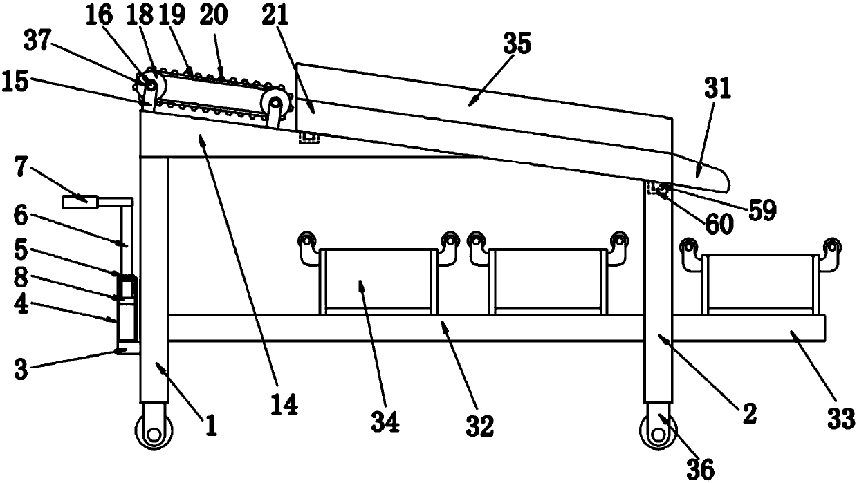
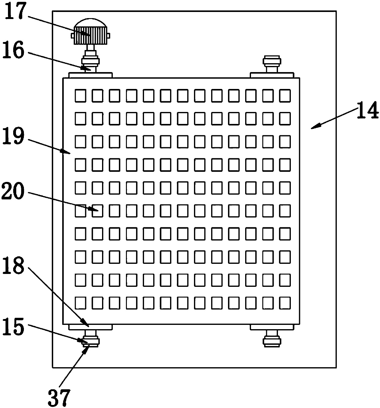
[0056] Embodiment one please refer to Figure 1-3 , a kind of pipe processing and classification equipment for municipal engineering, comprising a support plate a1 and a support plate b2, characterized in that: the upper surface of the support plate a1 is welded with a support block 14, and the upper surface of the support block 14 is respectively connected to four The bottom ends of the support rods 15 are fixedly connected, and the four support rods 15 are symmetrically arranged on the upper surface of the support block 14, and the opposite sides of the two support rods 15 are clamped with bearings a37, and the two bearings a37 are Socketed on the outer surface of the rotating shaft a16, and the outer surfaces of the two rotating shafts a16 are fixedly connected with transmission wheels 18, and the two transmission wheels 18 are connected through a transmission belt 19, and one end of the back of the rotating shaft a16 is connected to the drive motor 17 The output shaft is f...

Embodiment 2

[0058] Embodiment 2 Please refer to figure 1 , 4 , 5, the side of the support plate a1 is welded with a fixed block 3, the upper surface of the fixed block 3 is fixedly installed with a fixed cylinder 4, the upper surface of the fixed cylinder 4 is clamped with a sliding sleeve 5, and the sliding sleeve 5 The inner wall of the fixed rod 6 is sleeved with a fixed rod 6, the top end of the fixed rod 6 is welded with a handle 7, the bottom end of the fixed rod 6 is fixedly connected with the upper surface of the limiting plate 8, and both sides of the limiting plate 8 are A groove a9 is provided, and springs 10 are fixedly installed on the inner walls of the two grooves a9, and the opposite ends of the two springs 10 are respectively fixedly connected to the opposite sides of the two connecting plates 11, and the two connecting plates 11 The opposite sides are respectively fixedly connected to the opposite sides of the two pressure blocks 12, and the two pressure blocks 12 respe...

Embodiment 3

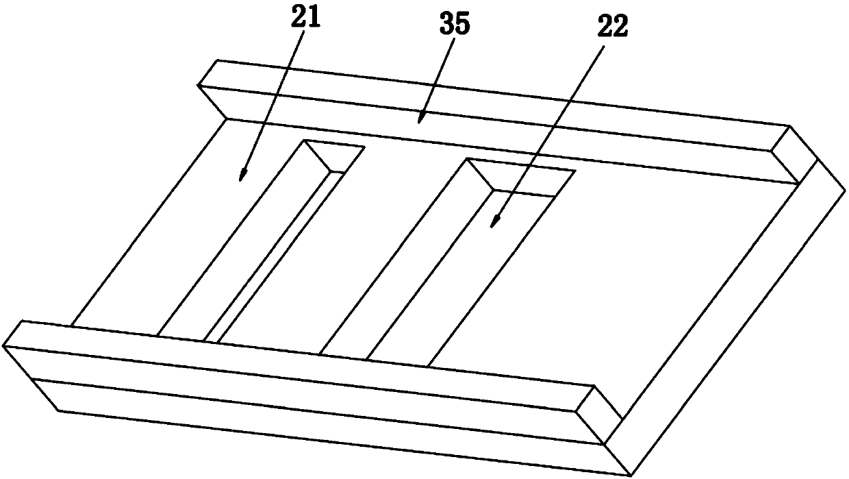
[0060] Embodiment three please refer to Image 6 A groove b23 is opened on the material guide plate 21 on the side of the material discharge port 22, and a movable plate 24 is arranged inside the groove b23. One side of the movable plate 24 is fixedly connected with the slider b41, and the slider b41 is slidably connected with the chute b42, and the chute b42 is opened on the material guide plate 21 on one side of the groove b23. A gap 25 is opened on one side of the material guide plate 21, and the movable plate 24 extends out of the material guide plate 21 through the gap 25, and is welded with a connecting block 26, and a bearing b38 is clamped on one side of the connecting block 26 , and the inner wall of the bearing b38 is sleeved with a rotating shaft b27, the rotating shaft b27 is fixedly connected with the threaded post 28, one end of the threaded post 28 is welded with a handle 43, and the outer surface of the threaded post 28 is threaded with a threaded cap 29 , the...


PUM


Abstract

The invention discloses pipe processing and sorting equipment for municipal engineering. The pipe processing and sorting equipment comprises a support plate a and a support plate b. The left side surface of the support plate a is welded with a fixed block, and a fixed tube is fixedly mounted on the upper surface of the fixed block. A sliding sleeve is connected to the upper surface of the fixed tube in a clamped mode, and a fixed rod is connected to the inner wall of the sliding sleeve in a sleeved mode. A handle is welded to the top end of the fixed rod, and the bottom end of the fixed rod isfixedly connected to the upper surface of a limiting plate. By arranging a driving motor, a transmission wheel, a conveyor belt, a material guiding plate, a discharge hole and material receiving boxes, after pipes are processed, the driving motor drives the transmission wheel to rotate to drive the conveyor belt to rotate, so that the pipes on the conveyor belt are conveyed to the material guiding plate; and the guiding function of the inclined material guiding plate is adopted, so that the pipes with small pipe diameters are first dropped from the discharge hole and collected into the material receiving boxes, and the sorting placement of the pipes with different pipe diameters is realized.

Description

technical field [0001] The invention belongs to the technical field of pipe material processing, and in particular relates to a pipe material processing and classification equipment for municipal engineering. Background technique [0002] Pipes are necessary materials for construction projects and are widely used in construction and municipal engineering projects. Commonly used are water supply pipes, drain pipes, gas pipes, heating pipes, wire conduits, rainwater pipes, etc. With the development of science and technology, the pipes used in home decoration have also experienced ordinary cast iron pipes, cement pipes, reinforced concrete pipes, and galvanized steel pipes. , plastic pipes and aluminum-plastic composite pipes, the pipes are often processed into pipes of different specifications, that is, pipes of different thicknesses and diameters during the processing process. [0003] After the original pipes are processed, the pipes are directly placed in the collection bo...

Claims


Application Information

Patent Timeline
Patent Type & Authority Applications(China)
IPC IPC(8): B07B13/07B07B13/14B07B13/16
CPCB07B13/07B07B13/14B07B13/16
Inventor 不公告发明人
Owner 江西佰嘉实业有限公司
Why Eureka
Try Eureka